


ELCOME Dear friends of protection and control engineering! In our new three-part series of technical papers, we devote ourselves intensively and extensively to the issue of earth-fault protection. Ground fault protection systems may not be one of the most complicated protective functions, but in practice there are always problems. There are many possible sources of error when it comes to verifying the correct directional decision. In our third and last part, wer'e gonna show you the most common methods for testing wattmetric earth fault relays.
Part 3: Testing of wattmetric earth fault relays
Wattmetrical earth fault protection systems detect the direction of the ground fault by means of the steady current and voltage signals during the earth fault. In this case, the angle between the measured zero-sequence voltage and the measured sum current is used to carry out a directional decision. The metrological difficulty here is usually due to the low continuous earth current (partially below 10 A primary), which can be superimposed on the load current. For this reason, a split-core CT is usually used for this method. It detects the sum of the current, whereby the symmetrical load currents are added to zero. As a result, cable type CT's with much smaller transmission ratios than those of the phase current transformers can be used. These are often 100 A, 60 A, 50 A or 40 A to 1 A. However, this measurement method is also very susceptible to asymmetries in the load currents. For this reason, it is generally not used in meshed networks. Therefore, the following explanations are also limited to a radiation network with a feed. The earth-fault direction is determined at the output fields of the substation.
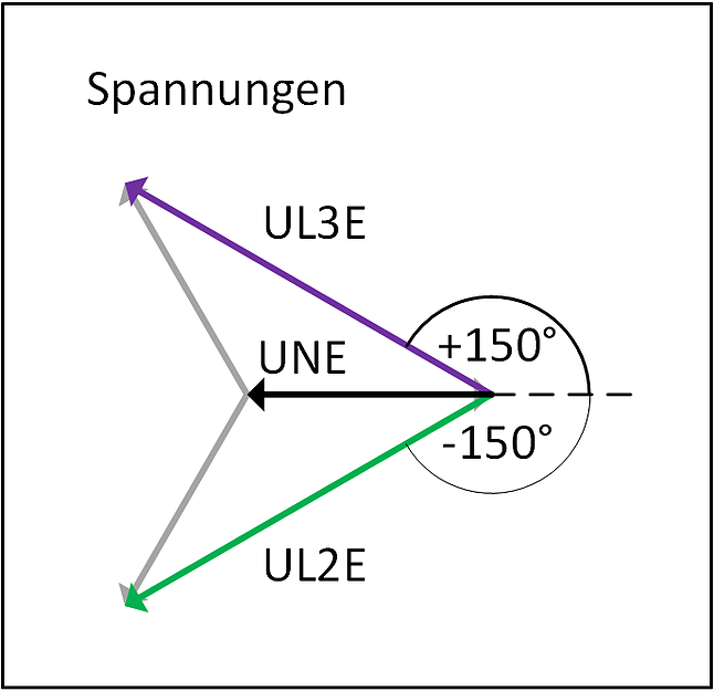
In order to be able to assess the behavior of a wattmetric earth-fault relay, it is important to know the vector diagram during an earth fault. As already described in part 1 of this series, a fully distorted earth fault is as follows: The phase-to-ground voltage of the faulty phase breaks down to almost 0 V. The phase-to-phase voltages remain unchanged. As a result, the phase-to-earth voltages are raised to the root (3) times the normal value, and the angle of these voltages increases to -150 ° or + 150 ° (instead of -120 ° and + 120 °, respectively). This behavior also produces a zero-sequence voltage between the star point and earth. This has an angle of 180 ° and corresponds to the magnitude of the phase-to-earth voltage in fault-free operation (note: the statement applies to the primary voltages only).
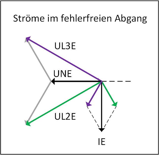
The earth fault current in the fault-free branches is caused by the capacities of the non-faulty phases. These generate currents which lead their driving voltages by 90 ° each. The sum of these phase currents leads the zero-sequence voltage by 90 °. In our vector diagram, this corresponds to an angle of -90 °.
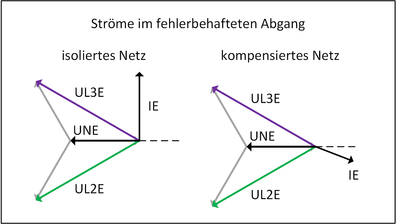
The currents in the faulty feeder depend on whether the network is operated in isolated or in a compensated manner. In the case of an insulated network, the current direction is rotated by 180° with respect to the fault-free branch. In the case of a compensated network, the current usually has a significant ohmic component (between + 90 ° and -90 °). In most cases, compensated networks are operated with overcompensation. The angle of the ground fault current is then generally in the range from -10 ° to -80 °.
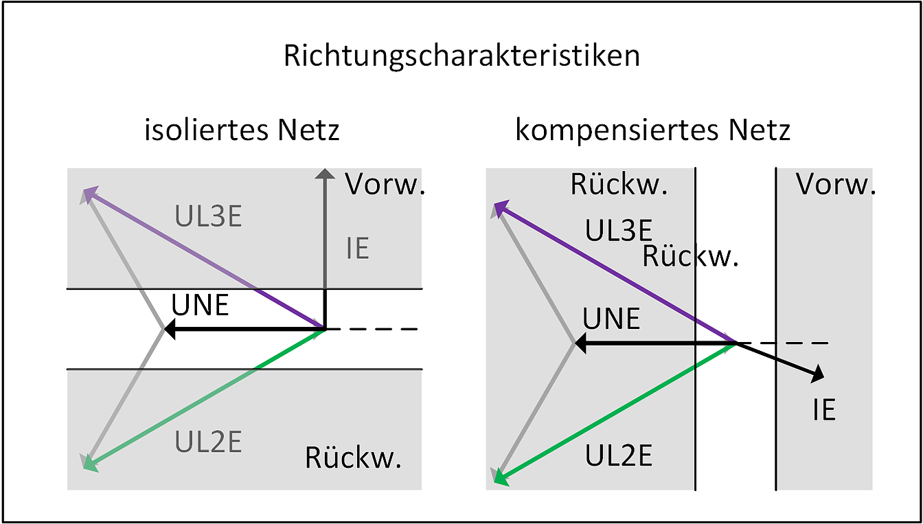
The characteristics which are used for the directional determination therefore differ depending on whether the network is operated in an isolated or compensated manner. In the case of isolated networks, the reactive component of the current is used (sinusoidal phi circuit) and the active component is used for compensated networks (cosine phi circuit).
In order to check the direction by means of a secondary supply, it is advisable to always use the same values. Here, the following is assumed: The secondary nominal voltage of the voltage transformer is 100 V / square-root (3). The zero-sequence voltage is measured by means of an open delta winding, which rated voltage is indicated by 100 V / 3. (Example: 20,000 V / square-root (3) to 100 V / square-root (3) to 100 V / 3). In addition, the current threshold is below 500 mA (secondary). A simple test can be established with these basic assumptions. The voltage values, as well as the magnitude of the current, always remain the same. Only the angle of the current is varied according to the test shot. Voltage specifications: UL1E = 0V @ 0 °, UL2E = 100V @ -150 °, UL3E = 100V @ 150 °, and UE = 100V @ 180 °. The value of IE is set to 500 mA here.
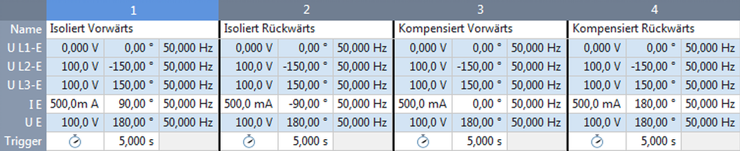
For an isolated network, one gets forward when IE has an angle of + 90 ° and backward when IE has an angle of -90 °. In the case of a compensated network, one obtains forward when IE has an angle of 0 ° or backward when IE has an angle of 180 °.
In order to determine the response values for UE and IE, this rule of thumb can of course also be used. For IE, the angle is simply set to "Forward" and the magnitude of the current is then increased step by step from 0 A. At UE, it is somewhat more complicated. The simplest way is to use symmetrical components. Simply set U1 to 57.73 V @ 0 ° and U0 to 0 V and 180 °. The angle of UE remains unchanged. At the same time, U0 of 0 to 57.73 V and UE of 0 to 100 V can be increased step by step. Most of the test modules of OMICRON are also able to automatically calculate the voltage UE. So you have to worry about one size less.
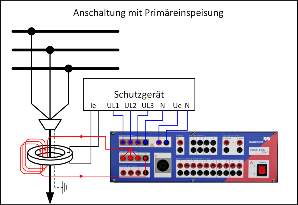
The test method described so far only covers the secondary feed. It is not able to detect wiring errors between the cable type CT and the protection device. In most cases, inverted lines do not attract attention immediately. In the event of a fault, this can lead to implausible directional indications, which makes the fault location considerably more difficult. In order to detect such faults, it is also a good idea to feed directly into the cable reassembly transformer on the primary side. Since here mostly no large currents are necessary, a secondary testing device is sufficient. If a little more current is required, you only have to pull the test strip several times through the transformer. Subsequently, feed from the busbar in the direction of the outlet. The angular relationships described above remain the same.
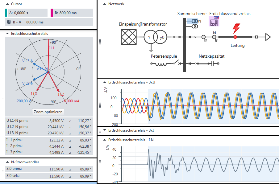
If you do not want to worry about the angular relationships, you can also use a network simulation. As already described in Part 2, the network parameters are entered here and the quantities in the earth fault are calculated automatically. In contrast to transient earth faults, not the transient but the steady-state current is important. The OMICRON test module for earth fault protection enables such a simulation in the above-described network configuration (one incomer, otherwise only outgoing feeders on the busbar). With OMICRON's RelaySimTest, the topology of the network can also be freely defined. Thus it is possible to check for each network whether the ground fault protection is correctly configured.
By the way, in order to gain reasonable conclusions in simulations-based earth-fault tests, it is usually not necessary to know the entire network parameters. The preset default values are generally sufficient.
In summary, it can be said that a secondary test of wattmetrical earth-fault protection devices is possible with simple means. A primary supply of the cable type CT's should be prioritized, because wiring errors are also detected. In addition, simulation-based approaches can be used to avoid the need to calculate the magnitudes of voltages and currents manually.
The methods described here refer to Omicron software and hardware, as we prefer to work with these tools. Other solutions can also lead to good results.
This also ends the third and final part of our series on the topic of earth fault protection. You have questions or suggestions: info@electrical-engineering.academy
Read also part 1: "Earth Fault Protection - How To Test Correctly?" and part 2: "Transient EF-Relay - How To Test Correctly?"
HEARTfelt Greetings Alexander Muth and Hannes Heiden
Safety Notice
Failure to observe the following points can result in death, serious injury or material damage!
Hazardous voltages may be present when carrying out the tests and checks described in this manual. The safety rules and regulations regarding electrical systems must be strictly observed at all times. The generator must always be shut down when working on the primary system; appropriate grounding and short-circuiting facilities are to be provided at the respective workplaces. When carrying out a primary check on a turbine set, take care to ensure that no overheating of the turbine occurs.
The work described in this manual may only be carried out by qualified personnel, who must be conversant with the relevant safety regulations and safety measures as well as the warnings in the manuals provided by the suppliers of the various components. The contents of this manual 10
must not construed as work instructions. All statements in this manual must be carefully considered in light of the safety rules and regulations. The information presented in this manual does not claim to be complete.


