


ELCOME Dear friends of protection and control engineering!
Today I show you a real example, which effect the inrush current of a transformer can have on the differential protection, although an inrush stabilization is activated. In addition, we learn valuable information on the subject of inrush-currents and in the end I am going to show you what to look for and how the crossblock function of the harmonic barrier is treated in best case. Here we go:
The problem:
When the 400 kV grid circuit breaker was switched on, a total of 4 transformers were connected simultaneously. The resulting inrush current led to the tripping of the differential protection function of the BBT03 auxiliary transformer, even though an inrush stabilization in the 7UT513 protection relay was activated.
The configuration:
We are located in a thermal power plant in Germany. The arrangement includes a 500 MW generator in block operation with a unit transformer, 3 auxiliary transformers and an adjacent 400 kV transmission network. The following figure provides an overview of the configuration:
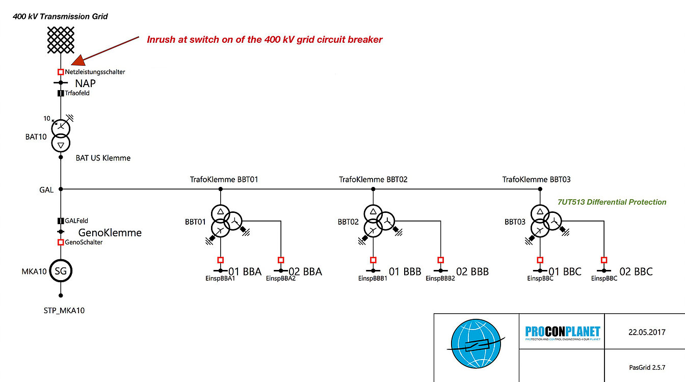
The 500 MW generator and the generator terminal leads (GAL) have a nominal voltage of 20 kV, the undervoltage sides of the three auxiliary transformers have a nominal voltage of 10 kV. The third voltage level in the model is represented by the 400 kV transmission network.
The scenario:
At the time before the switching operation, the generator was at standstill (GLS OFF), the 10 kV feeds of the 10 kV busbars of the auxiliary transformers were also switched off. By switching on the 400 kV grid circuit breaker (NLS), the four transformers BAT10, BBT01, BBT02 and BBT03 should now be connected. The resulting inrush current led to the protection trip of the 7UT513 of the BBT03, although a switch-on stabilization in the protective device had been active.
The switch-on rush in theory and practice:
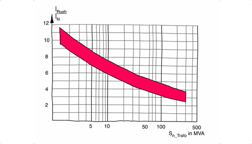
The switch-on of transformers leads to inrush currents. These are mainly dependent on the power of the connected transformers. In case of smaller transformers, the so-called Inrush currents can reach values of up to 14 times of the nominal transformer current, but they fade away within a few milliseconds. In the case of larger transformers, inrush currents are usually in the range of a few hundred milliseconds. The shape of the current curve is characterized primarily by the bias (remanence) and the moment of switch-on time. The following diagram gives an approximation of typical inrush events (The figure comes from the book "The Bible of Generator Protection").
In the further course of time, the amplitudes of the inrush current are reduced to the stationary magnetization current. Since the inrush has sinusoidal halfwaves with 180° interruptions, the even-numbered halfwaves are particularly pronounced. This issue is now used within the protective relay algorithms to close by means of significant 100 Hz components on a switching-on process and release the inrush current stabilization function.
The protection system:
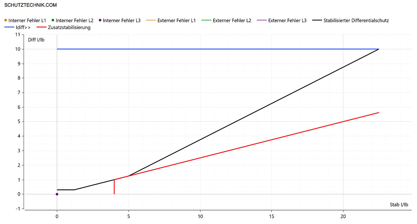
The BBT03 auxiliary transformer ist equipped with a digital differential protection device from Siemens. It's a Siprotec 7UT513 with 3 sides (three-winding transformer). The device is connected on all three sides with 2500/1 A current transformers (5P20 at 20 VA) and is parameterized as follows:
🌐 I Diff > = 0,3 I/Ib
🌐 t Diff > = 0 s
🌐 I Diff >> = 10 I/Ib
🌐 t Diff >> = 0 s
🌐 I Stab base point 1 = 0 I/Ib
🌐 Rise 1 = 0,25
🌐 I Stab base point 2 = 2,5 I/Ib
🌐 Rise 2 = 0,5
🌐 Block via 100 Hz (2. Harmonic) = 15 %
🌐 Block via 250 Hz (5. Harmonic) = 30 %
🌐 Disengaging time = 0,2 s
🌐 Crossblocking = No
The following figure shows the resulting characteristic curve:
Due to the galvanic coupling of all devices (all transformers plus generator), the tripping of the BBT03 differential protection system leads to the shutdown of the entire power unit block, to the trip of all 10 kV switches, the generator circuit breaker and the 400 kV grid circuit breaker.
The analysis:
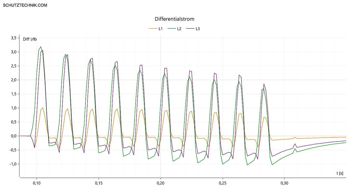
Let's look more closely at the fault record. In the following figure, we first see the curve of the inrush current, measured on the 20 kV side of the BBT03.
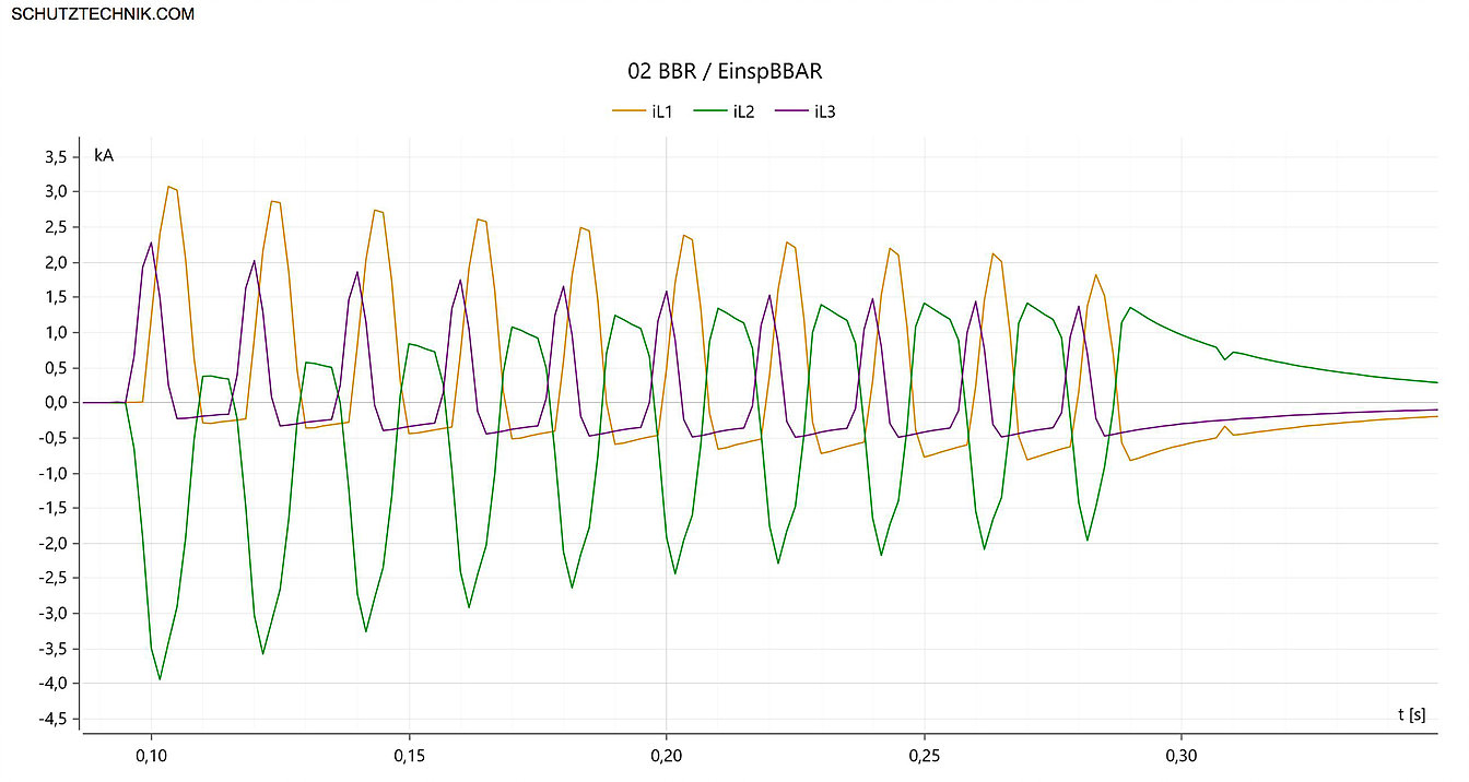
The largest peak can be observed in phase P2 (green), where the inrush with 4 kA is 3 times as much as the nominal current of the transformer. The entire current flow takes about 300 ms. The 180° gap between the three phase currents can be clearly seen. This results in the 100 Hz component, as described above. The protective relay has an included inrush stabilization function, which blocks the tripping from 15% of the second harmonic (100 Hz). The important question must therefore be clarified:
Why didn't the stabilization stabilize?
Let us first consider the differential current:
A pronounced diff current can be seen in the two phases P2 and P3 (green and violet). It is important to see how these curves behave in relation to the stabilizing current and whether the tripping range of the differential protection characteristic is achieved. In the following two videos, we look at the Diff / Stab event over time.
In the following video we can see the curves again in the larger zoom:
It is easy to see that the diff-stab profiles of the two phases P2 and P3, lying on the inner failure characteristic, going far in the triggering range of the diff-stab characteristic. In addition, it can be seen that even the values of phase P1 slightly extend into the tripping region. Back to our important question:
Why did not the stabilization stabilize?
Let us look at the second harmonic:
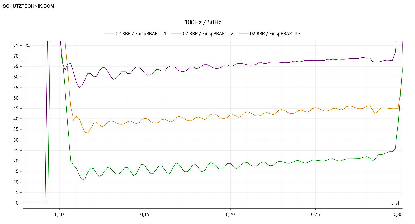
The 100 Hz components of phases P1 and P3 (yellow and violet) are at a safe distance above the setting value of 15 %. In Phase P2, however, this looks different. After the very first peak has passed, the response value for the switch-on stabilization is cyclically undershot for the following 5 mains periods (approx. 100 ms). Here it happens. Since the differential protection, including inrush stabilization, is self-sufficient for each phase, the blocking of the tripping is rendered ineffective by the non-filling of the 15% criterion in phase P2. The protective device triggers as expected.
By activating the cross-blocking function, this undesirable triggering could have been prevented. When the cross-blocking function is activated, exceeding the response value of the inrush stabilization in one single phase leads to the blocking of all three phases. The following figure shows the logical difference between inactive and active crossblocking.
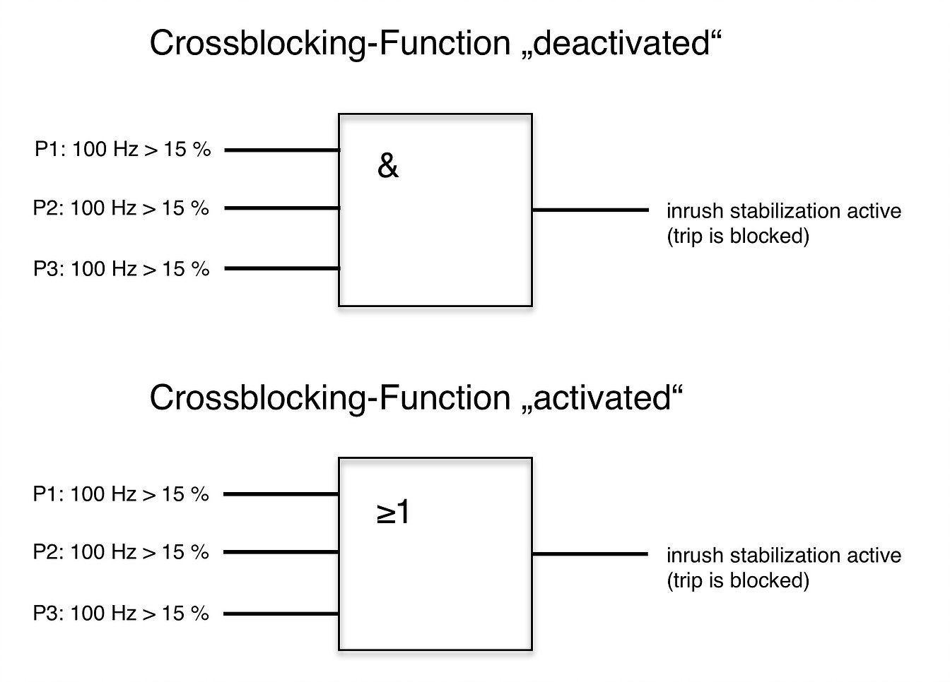
Now one could mean: "Activate crossblocking and the thing is done". It is not that simple. We must bear in mind that the most common transformer faults occur during the switching-on moment. There is now a great danger that the activation of the crossblock function will lead to a subfunction or to a protection failure. As mentioned, if one of the three phases leads to more than 15% of the second harmonic or reaches the set threshold value, the releases of all other phases are also blocked.
Taking this circumstance into account, modern digital relays are capable of limiting the cross-blocking function for a certain time range. In our example, a crossblocking activation for 5 network periods would already have led to the successful stabilization of the differential protection. When switching to a short circuit or a short-circuit event at the moment of switching-on, however, these valuable 5 network periods would add to the error-clarification time in sum. 100 ms more or less can already be the "game changer" for larger oil transformers.
In our practical case, the decision is not very difficult. Since the 7UT513 from our example did not have the time limitation of the crossblocking function, we decided against the activation of the crossblocking function.
It is important to consider the importance of stabilized power-up by means of cross-blocking and which delay is chosen. My tip: In doubt, the crossblocking function should always be deactivated, at least it should be treated with respect. If the crossblocking function is activated, then you should pay attention to a very short time limitation of the function and to a meaningful setting of the I Diff >> stage, which is not affected by the switch-on stabilization.
The alternative may be the loss of valuable clarification time up to the total fail of the main protection function on high-quality primary components. As a service provider, it is also useful to involve the plant operator and / or supplier in the decision process of this imporant setting.
HEARTfelt Greeting Alexander Muth


