


EARTfelt Greetings, dear friend of protection and control engineering, "Learning the basics" is the tip of Dr. Ing. Gernot Druml, to the question "What advice can you give other engineers?". We agree with this opinion and devote ourselves today to a very special harmonic, namely the 3rd harmonic.
What is so special about this harmonic?
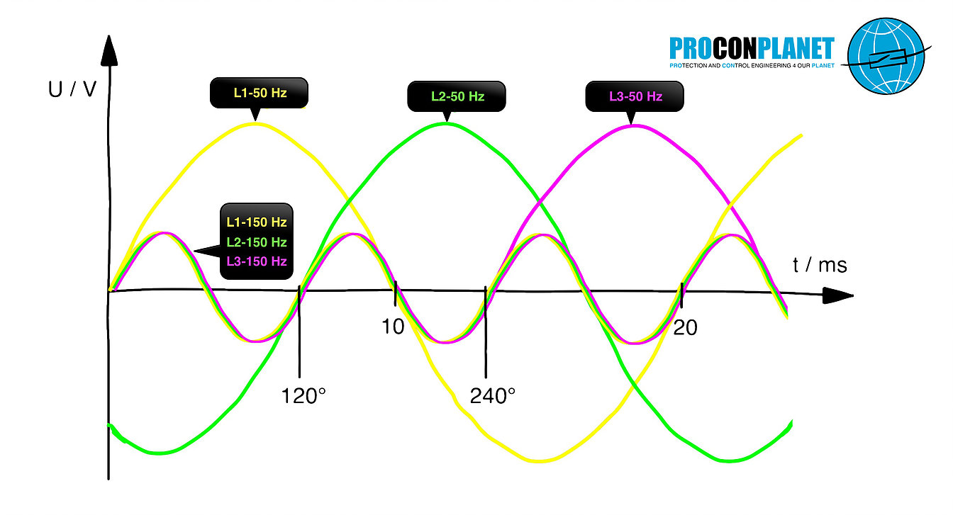
First of all, nothing. The ordinal number 3 describes that this harmonic is 3 times the frequency of the fundamental. In our classic 50 Hz system, that is correspondingly 150 Hz. That means:
"Each phase goes through 3 full periods, within a grid period (within 20 ms with a fundamental of 50 Hz)".
Furthermore, we note:
The third harmonic is odd. This, too, is not exactly a unique selling proposition. The peculiarity of the third harmonic only becomes apparent, when we take a closer look at the zero system of the symmetrical components. Symmetrical what? Here we go:
Symmetrical components
To evaluate and calculate unbalanced three-phase systems, these are converted into three single-phase symmetrical systems. The three resulting symmetric systems are:
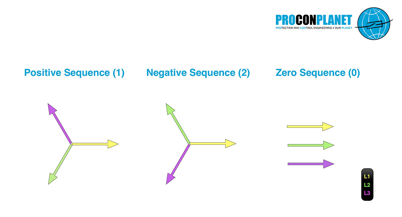
🌐 Positive Sequence-system (1): The three phases of the Positive Sequence-system are phase-shifted by 120 °. The Positive Sequence-system has the designation index 1.
🌐 Negative Sequence-system (2): The three phases of the Negative Sequence-system are also phase-shifted by 120 °, albeit with opposite rotation, in relation to the positive sequence. The negative system has the index 2.
🌐 Zero Sequence-system (0): The phases of the Zero Sequence-system, all have the same phase position. The zero system has the designation index 0.
The following figures show the three symmetrical component systems:
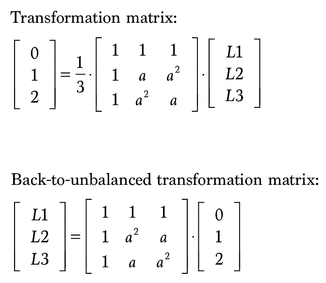
To transform an unbalanced three-phase system into the three symmetric systems and reverse the operation, we use the following matrices. Symmetrization takes place here by multiplication of the natural column vector with the symmetrization matrix. These as well as the desymmetrization matrix contain the versor a, which causes nothing more than to rotate the multiplied phase by 120 °. The inverse transformation takes place in accordance with the Back-to-unbalanced transformation matrix.
So let's take a look at the zero system.
In order to realize a transfer of three phases into the zero system, these are multiplied by 1, added vectorially and then divided by 3. We can the multiplication by 1 let happen, what remains is the vectorial addition and the factor 1/3.
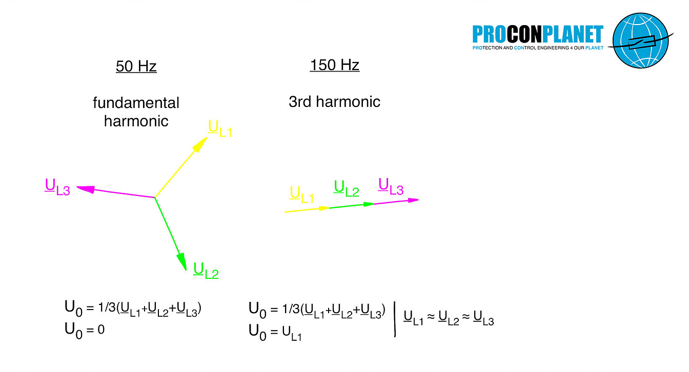
If we now add the three phases of a "healthy", ie completely symmetrical three-phase system vectorially, the sum always equals 0. This applies to the 50 Hz fundamental, as well as to the second, to the fourth and also to the fifth harmonic.
And with that we have arrived at the mystery of the third harmonic.
The zero system of a symmetrical 150 Hz harmonic is always present. Even in faultless condition, the proportion adds up. The reason for this is shown in the following figure:
The phases of the third harmonic, always go through the zero crossing, of one of the phases of their fundamental. As a result, all 3 conductors are congruent in phase. In the formation of the zero system, three pointers identical in magnitude and in direction are now added vectorially, which leads to the corresponding tripling of the simple phase value. This situation is shown again in the figure below in the form of pointer images.
Cui bono - or "who benefits"?
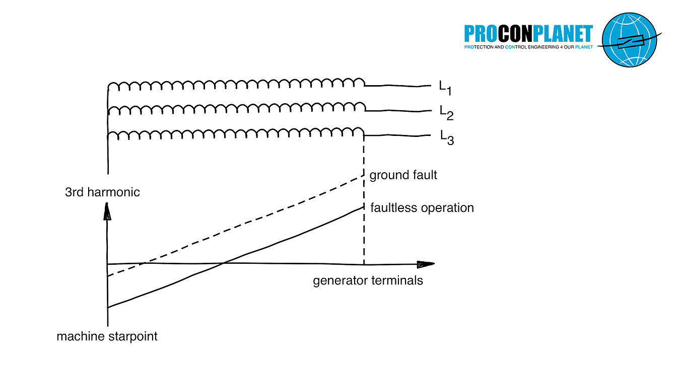
The most important application of the third harmonic is the detection of generator earth faults. Depending on the design of the poles of a generator, 150 Hz harmonics are produced in the stator winding. If the machine produces a sufficiently large 3rd harmonic, then this is relatively easy to find in the zero system.
When a ground fault occurs in the stator winding of the generator, the distribution of the parasitic capacitances changes. This affects our measured values. When the ground fault occurs, the 3rd harmonic in the star point reduces (collapses to about 0 V) and increases on the generator terminals. Depending on the measuring point, this means that the zero sequence system can be supervised using an undervoltage or overvoltage protection function. The following figure shows the trend of the 3rd harmonic in the zero system in case of fault entry.
The disadvantages of this method are:
🌐 Not every machine generates sufficient harmonics
🌐 The 3rd harmonic is both active and reactive power dependent and thus variable depending on the operating point.
To verify the starting of the protection, a load test is obligatory.
Conclusion
We have seen that the 3rd harmonic is present in the zero system even at 100% symmetrical three-phase conditions, in the fault-free state. The reason is that all three phases are exactly in phase. Incidentally, the same applies to all multiples of the 3rd harmonic, that is, to the 6th, 9th, 12th, 15th ... harmonic and so on.
In a further contribution we will discuss the big drawbacks of the 3rd harmonic and its multiples, in terms of network perturbations. The presence in the zero system leads to enormous loads of the return conductor and local transformers have to be dimensioned larger due to harmonic components. However, this is worth a separate contribution.
We hope our new basic contribution has helped you, for many of you it was certainly a refresher, also that should have been worthwhile.
Here you can find the full interview with Dr. Gernot Druml.
Have fun and HEARTfelt Greetings Alexander Muth


