


EARTfelt Greetings, Dear friends of the protection and control engineering! Checking the expected behavior of protective devices already in the network model has always had its charm, but also its limits. How much protection modeling is currently going on in terms of overcurrent time protection?
In our two-part guest article André Latarius shows you how you can realize the reverse interlocking with the software PowerFactory.
Enjoy reading, we pass on:
André Latarius

Implementation of backward locking with PowerFactory (part 1)
In this article it is shown that with the help of the network calculation software PowerFactory protection systems can be designed and their selectivity can be proven. For this purpose, the application of directional overcurrent protection is examined in a simple example network without the protection devices communicating with each other. In the second part, the communication between the protective devices is then implemented in the identical network.
1 part: Directed UMZ protection
For an overview, the network under consideration and the setting data of the protective relays are shown in Fig. 1. The software makes it possible to emulate the protection devices and instrument transformers and thus to simulate the behavior of the network in the event of a fault.
The aim should be further that fault locations can be placed anywhere in the network and the correct design of the relay can be reconstructed.
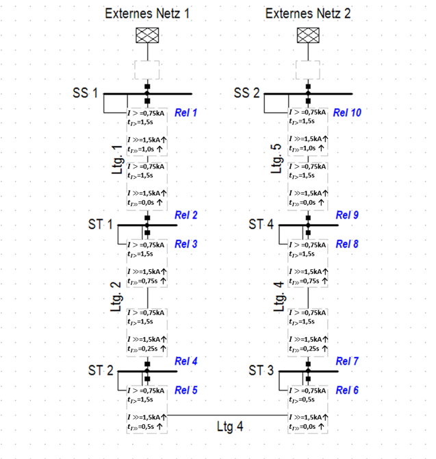
Fig. 1: Overview of the network and setting data of the protection relays
Before the protection system can be examined, all necessary protection devices must be integrated into the existing network model. For the example study considered, a generic relay model is used with four possible overcurrent stages, of which only two overcurrent stages are activated, Figure 2.
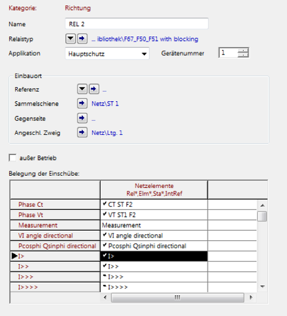
Fig. 2: Options and transformer assignment of the relay model used
In principle, it is possible to choose between two different calculation types, the simple short-circuit current calculation and the incremental short-circuit current calculation.
In the simple short-circuit current calculation, an failure is placed anywhere in the network. Depending on the fault currents that occur, the software calculates the resulting tripping times, which can be read from the result boxes. It can be seen that the first protection relay (Rel 1) triggers after 1 s, as desired. The opposite relay triggers immediately. The shutdown of the error takes place as expected selectively.
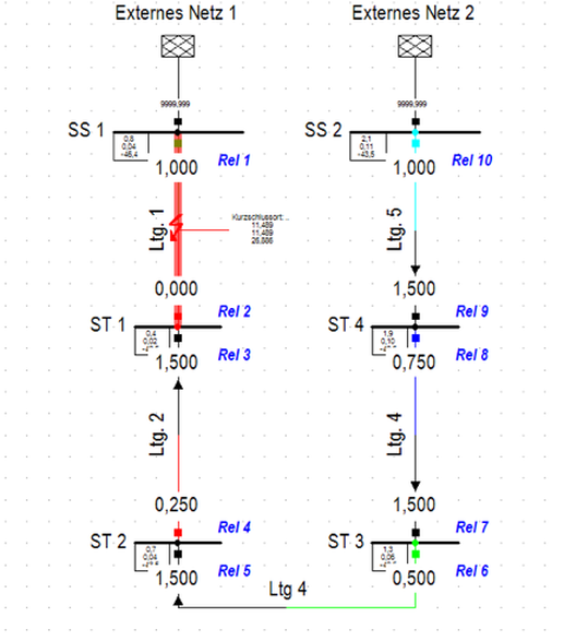
Figure 3: Short circuit on line 1 and resulting reaction times
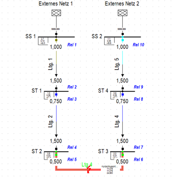
Figure 4: Short circuit on line 4 and resulting reaction times
Advantage of the first calculation is, that for reports and similar a descriptive evaluation is possible. In addition, specific triggering times can be assigned an individual coloring. Especially with more complex network structures, the graphical coloring can simplify the traceability of a selective triggering.
As a second calculation option, a stepwise short-circuit current calculation is presented. It makes it possible to examine the protection scheme step by step in response to an error. A new step is always defined when there is a change in the network state.
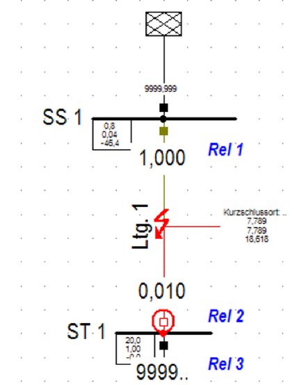
Fig. 5: Calculation stepwise, first time step, trip of relay 2 after 10 ms
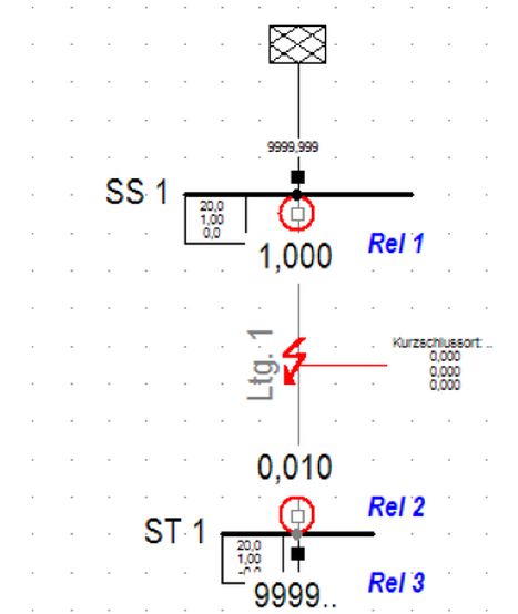
Fig. 6: Calculation stepwise, second time step, tripping of relay 1 after 1 s
The advantage of this calculation variant is that the distribution and size of the short-circuit currents is recalculated after each triggering of a switch. Furthermore, a tolerance in the triggering can be specified, for example, switch delay times or delays during the communication and processing of signals can be taken into account. If a switch is blocked, the design of the backup protection can be checked. This is blocked in Figure 7 of the circuit breaker 2.
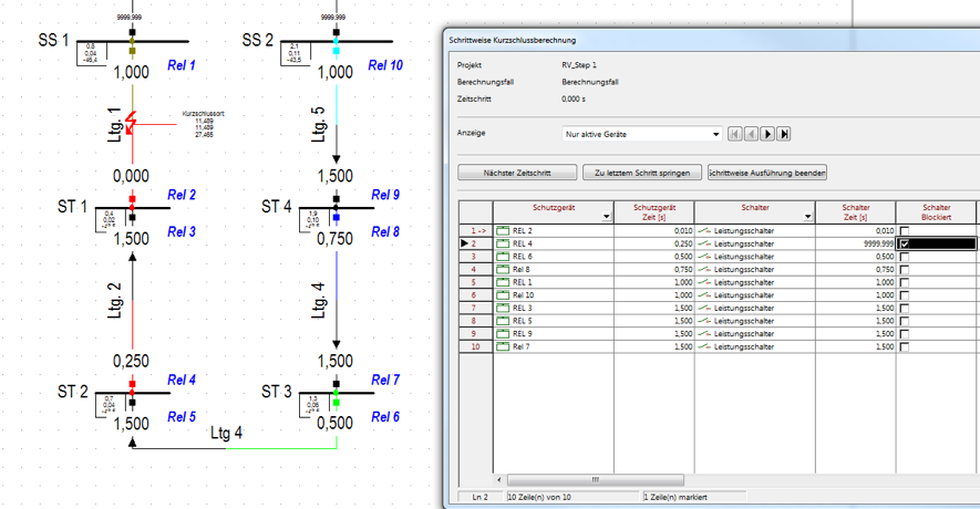
Figure 7: Blocking of LS 2 in the event of a short circuit on line 1 | Check backup protection
Figure 8 shows that the circuit breaker does not work as desired. The protection concept provides that in this case the downstream circuit-breaker triggers after a delay time of 250 ms. As expected, this triggering also works, as shown in Figure 8.
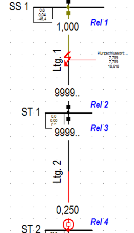
Figure 8: "Time step 250 ms", relay 2 has blocked, relay 4 trips after 250 ms
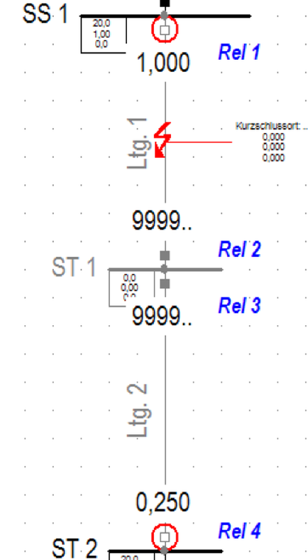
Fig. 9: "Time step 1000 ms", relay 1 triggers as expected
Outlook Part 2: Communication of the UMZ protection devices
The attentive reader has certainly noticed that this protection concept has major disadvantages for larger networks. On the one hand, it is not possible to realize short fault clearance times and to arbitrarily increase the number of fault sections in two-sided networks without the other protection relay being used.
Therefore, in the next part the communication of the relays with each other will be presented. This makes it possible to realize a backward locking of UMZ relays and to realize much larger networks with the presented protection concept with a short error explanation time.
André Latarius

Mr. M.Sc. Latarius is a project engineer at IEK GmbH. His main focus is on the modeling and analysis of electrical networks with regard to primary and secondary technical topics.
Contact: andre.latarius@iek-cottbus.de


