


esting Undervoltage Dependent Directional Reactive Power Protection HEARTfelt Welcome, dear friends of protection and control engineering,

Today we present a guest article for the first time in the history of our platform proconplanet. We are very pleased with the contribution of KoCoS Messtechnik. The paper describes the testing of the Q-U-protection function using the ARTES test device.
A look at the state of energy development shows how important this issue is at present. In recent years, regenerative energy generators have become increasingly important. Particularly in the area of wind energy there were enormous gains. At the end of 2015, the installed capacity of the plant was 45 GW. Individual plants now have installed power between 5 and 8 MW (onshore / offshore).
So let's get started with our first guest contribution, this time by KoCoS Messtechnik AG:
Automatic Testing for the Undervoltage Dependent Directional Reactive Power Protection Function
Copyright: KoCoS Messtechnik AG
Authors: Rijanto / Bitz
As the capacity of individual wind turbine generator systems increases, they are connected to medium as well as high voltage electrical power systems directly. In order to safe-guard the stability and therefore the safety and reliability of electrical power systems, a power generating system (PGS) may no longer be disconnected from a power grid as soon as a short-circuit causes a voltage dip to occur, as was stipulated by grid codes in the past. The aim of this is to avoid disconnecting other wind turbine generator systems located further a eld.
Before a PGS can be put into operation, certification must be obtained to demonstrate that it is fit for this specific purpose. The certification procedure has been described in [2]. During certification, various tests must be carried out, including verification that the protection concept functions as intended. Up until now, tests of this type could only be carried out manually and required lengthy preparations and calculation of test conditions. Results must be documented separately too. This paper describes how to test the Q-U protection function and generate an appropriate test report at the same time using an automatic test system.
1 Undervoltage-dependent
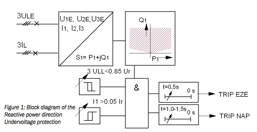
For the safe operation of electrical power systems with a high proportion of decentralized PGSs, it is necessary for individual power generating units (PGUs) to contribute to power grid support. If, for example, there is a short-circuit in the electrical power system, the Euro- pean Network of Transmission System Operators for Electricity stipulates that PGUs must be disconnected from the grid with a time delay of 0.5 s if the voltage at the grid connection point (GCP) decreases and remains at 0.85 of the rated voltage and if reactive power is si- multaneously consumed [3]. Similar requirements have been laid down by the German Association of Energy and Water Industries in the technical guideline for PGSs in medium-voltage networks [4], but disconnection is to be performed at the GCP. The equipment for decoupling the PGS from the electrical power system, which is required in order to fulfil this stipulation, is known as an undervoltage dependent directional reactive power relay (Q-U protection). The specifications for Q-U protection [5] describe in detail how the required function works. The secondary legislation to the German Renewable Energy Sources Act (EEG) requires that this type of Q-U protection be installed [6]. The block diagram of the Q-U protection function is shown in Figure 1.
2 Testing the Q-U-Protection function
According to [7], the minimum requirement is for the following tests to be carried out:
• Test the protection relay setting with regard to the detection of the power ow direction at the GCP. The following procedure is recommended:
· When there is enough wind, the wind park feeds electrical power into the grid. According to the load reference arrow system, the sign prefixing the electrical active power should be negative in this situation. So the correct connection of the wiring should be checked first.
• Test symmetrical voltage dips:
· With reactive power greater than 5 % of the rated value and a specified acitve power which is defined by a minimum current I1>, the voltages are to be decreased symmetrically until the Q-U protection function starts.
· The start/operating time has to be recorded.
• Determine the resetting ratio:
· Before the Q-U protection function operates, the voltages are to be increased symmetrically again until the Q-U relay is reset.
• Test the AND link:
· Apparent power is to be provided at a level which is sufficient for the directional operating characteristic of the reactive power to respond. The voltages are then to be decreased asymmetrically. Even when one phase-to-earth voltage is decreased to 0 V, the Q-U relay should not operate.
• Test relay operation in specified direction of the reactive power· The operating characteristic for the reactive power in relation to the active power is to be tested.
• Test the release current· The size of the release current is to be ascertained.
It should also be mentioned that the VDN guideline for digital protection systems [8] requires that installed protection systems be tested at regular intervals to ensure that they functioncorrectly. In this guideline a four year test cycle is recommended.
3 Test system
The use of a fully automatic test system with appropriate testing software substantially reduces the amount of time it takes to test the Q-U protection function.

Figure 2: Test system ARTES 560
Figure 2 shows the ARTES 460 test set whose technical specifications fulfill all the requirements needed in order to test the Q-U protection function. The test set is operated and controlled with the ARTES testing software. ARTES V4, the latest version of the software to be released, includes the QU-Monitor, a test module which has been specially designed for testing the Q-U protection function. This test monitor simplifies, automates and significantly speeds up the test process.
Figure 3 shows the ARTES V4 testing software with the new Microsoft Fluent user interface.
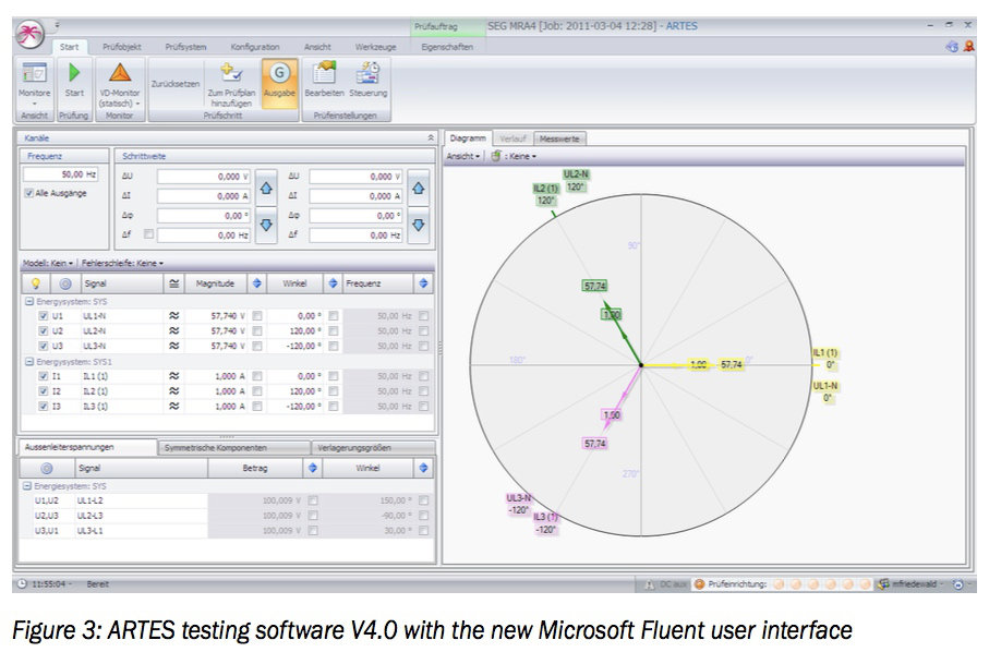
This interface provides fast access to all the functions of the testing software. The illustration shows the VD-Monitor which is included in the standard delivery package. This basic module can be used to test any type of protection relay by setting the generator values manually.
The ARTES testing software features a wide range of convenient test monitors which have been specially developed for testing specific protection functions. Undervoltage dependent directional reactive power protection is included in the list of functions displayed under Functions/Configuration shown in Figure 4.

Because it is very easy to adjust the characteristic in the software, it is possible to test all the various different response characteristics for the Q-U function which have been implemented by the manufacturers of protection devices. Figure 5 shows the possible characteristics of the reactive power as a function of the active power.

As can be seen in the illustration, the following options are taken into consideration:
• Constant or minimum reactive power
• Rising reactive power after release through minimum current
• 2-stage reactive power after release through minimum current
• 3-stage reactive power after release through minimum current
By way of example, Figure 6 shows the equivalent circuit diagram with the instrument transformers and their transformation ratios.
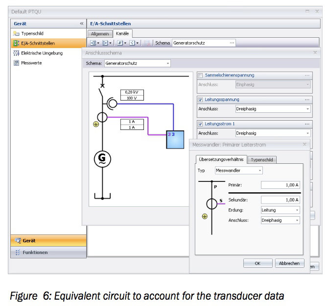
The test values which are needed in order to carry out a function test (undervoltage, reactivepower and minimum current) are calculated automatically taking the instrument transformer data into account.
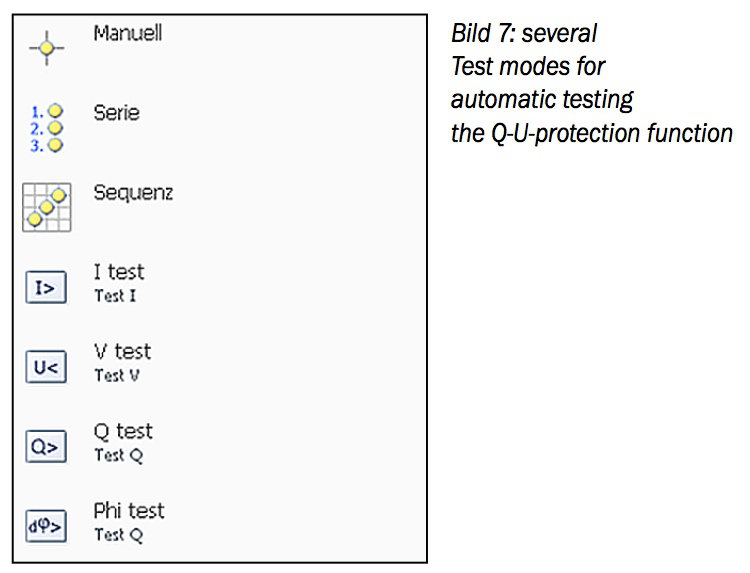
FA range of different test modes are available for configuring the test steps needed. Test definitions based on different test modes can be grouped together in one test plan and carried out automatically (Figure 7).
First use the „manual“ test mode to check that the protection device is connected correctly. The protection device is generally connected as shown in Figure 8.

The current transformer is usually earthed on the S1 side or line side respectively. When the PGS produces active power, a negative active power value must be displayed.
The ARTES 460 test system is to be connected up appropriately and the earthing of the device under test is to be defined on the line side. When an apparent power value with positive active and reactive power is set, the sign prefixing the active and reactive power on the display of the protection device must be negative.
The „series“ and „sequence“ test modes are then used to test the accuracy of the operating characteristic of the reactive power as a function of the active power. Test points can be defined freely in accordance with the type of operating characteristic implemented by the manufacturer of the Q-U protection function. When a test is started, the test points are dealt with one by one and evaluated according to the reaction of the Q-U protection function. In the other test modes, the settings listed below can be tested automatically, taking into account the appropriate test conditions for the Q-U protection function.
• V test: test the starting value of the undervoltage setting
• I test: test the starting value of the minimum current setting
• Q test: test the starting value of the reactive power
• φ test: test the angle of the reactive power direction
The starting and reset values are determined using pulse ramps. All the parameters required for the test, such as start and end values, pulse width, angle between current and voltage, number of steps, pause values etc., are defined in a dedicated area of the workspace. The values can be given in relation to the rated value or as absolute values. No conversion is required. The reset values are also determined automatically and the corresponding reset ratios identified.
In „V test“ mode, it is also possibleto select fault loops, enabling phase-selective fault types to be reproduced. This makes it possible not only to determine the starting value of the U< function but also to determine the logical AND-link, as required above, in one and the same test step.
In „φ test“ mode it is possible to test the reactive power range in both a clockwise and anti-clockwise direction. As a result, the starting behaviour can be determined in the 4 quadrants of the Cartesian coordinates. Once the automatic test has been completed, the test report generated by the ARTES testing software can be submitted for assessment within the certification process for the wind turbine generator system.
The results are presented both graphically and numerically. The test steps defined for the test can be saved in a test plan together with the test results, allowing the behaviour of Q-U protection functions to be compared again when the test is repeated later at appropriate regular maintenance intervals.
4 Summary
For the safe operation of electrical power systems with a high proportion of decentralized PGSs, it is necessary for individual power PGUs to contribute to power grid support. The equipment for appropriately decoupling the PGS from the electrical power system which is required for this purpose is known as Q-U protection. The secondary legislation to the German Renewable Energy Sources Act (EEG) requires this type of Q-U protection. In order to reduce the amount of time it takes to test the Q-U protection function, considering the large numbers of wind turbine generator systems, an automatic test system is required.
An automatic test for the Q-U protection function is already a component of the ARTES V4.0 testing software. This testing software is backwards compatible with earlier versions of the ARTES testing software. The various test modes for the test steps required can be grouped together to form a test plan for automatic execution of the Q-U protection function test. Test plans can be de ned appropriately and saved for the repeat tests which should be carried out at least every 4 years.
5 Literature
[2] H. Hartenbach, H. Rijanto, J. Möller: Automatic certification testing of the system automatics of wind power plants, paper 0418, CIRED 2011
[3] VDN: Transmission Code 2007, Netz- und Systemregeln der deutschen Übertragungsnetzbetreiber, Version 1.1, August 2007
[4] BDEW: Technische Richtlinie „Erzeugungsanlagen am Mittelspannungsnetz“, Richtlinie für Anschluss und Parallelbetrieb von Erzeugungs- anlagen am Mittelspannungsnetz, Ausgabe Juni 2008
[5] VDE/FNN: Lastenheft Blindleistungsrichtungs-Unterspannungsschutz (Q-U-Schutz), Ausgabe Februar 2010
[6] Verordnung zu Systemdienstleistungen (Systemdienstleistungsverordnung – SDLWindV) zum EEG 2009, Ausgabe Mai 2009
[7] J. Möller: Anforderung an die Schutzprüfprotokoll des Entkupplungsschutz, Stand 23.01.2011, www.moe-service.com
[8] VDN: VDN – Richtlinie für digitale Schutzsysteme, Berlin, Ausgabe November 2003
[9] KoCoS: ARTES II Automatische Prüfsysteme
Safety Notice
Failure to observe the following points can result in death, serious injury or material damage!
Hazardous voltages may be present when carrying out the tests and checks described in this manual. The safety rules and regulations regarding electrical systems must be strictly observed at all times. The generator must always be shut down when working on the primary system; appropriate grounding and short-circuiting facilities are to be provided at the respective workplaces. When carrying out a primary check on a turbine set, take care to ensure that no overheating of the turbine occurs.
The work described in this manual may only be carried out by qualified personnel, who must be conversant with the relevant safety regulations and safety measures as well as the warnings in the manuals provided by the suppliers of the various components. The contents of this manual 10 must not construed as work instructions. All statements in this manual must be carefully considered in light of the safety rules and regulations. The information presented in this manual does not claim to be complete.


