


elcome dear friends of protection, control & electrical engineering. Can current transformers be significantly impaired in their measurement accuracy by small parasitic DC currents? In an exciting technical article, our guest author Roland Bürger (SENSELEQ) investigates this question in depth, shows possible causes and has an interesting answer ready. Have fun while reading!
Parasitic DC currents in AC systems and their effects on inductive current transformers
Introduction
Inductive current and voltage transformers are mainly used in all voltage levels of the electricity network. A wide range of measurement and protection measurements are realized by these transformers. In the field of billing measurements, current transformers are mainly used with accuracy classes 0.1 and 0.2S. While the effects of DC components in the AC signal on power transformers are described in detail in the literature, current transformers will be considered in more detail in the following. In addition, various parasitic DC sources will be discussed.
GIC (Geomagnetically Induced Currents)
Parasitic DC currents can couple into the AC system from different sources. One natural source that cannot be influenced by humans is the sun. The sun consists of a plasma composed of negative electrons and positive ions. This plasma is in constant motion in the outer zone due to convection currents. The electrons have a higher velocity than the ions because of their lower mass. An electric current flows, which induces a magnetic field. In some cases, this causes magnetic field tubes to bulge outward. When these tubes twist into closed loops, the magnetic field lines close briefly, and there is an abrupt change in the structure of the magnetic field and large amounts of energy are released (magnetic reconnection). This phenomenon is probably responsible for solar flares. Due to the opposite orientation of the magnetic field, the loop with the enclosed material is ejected. This coronal mass ejection (CME) consists mainly of electrons, protons and to small parts of nuclei of heavy elements like helium, oxygen and iron and is electrically conducting.
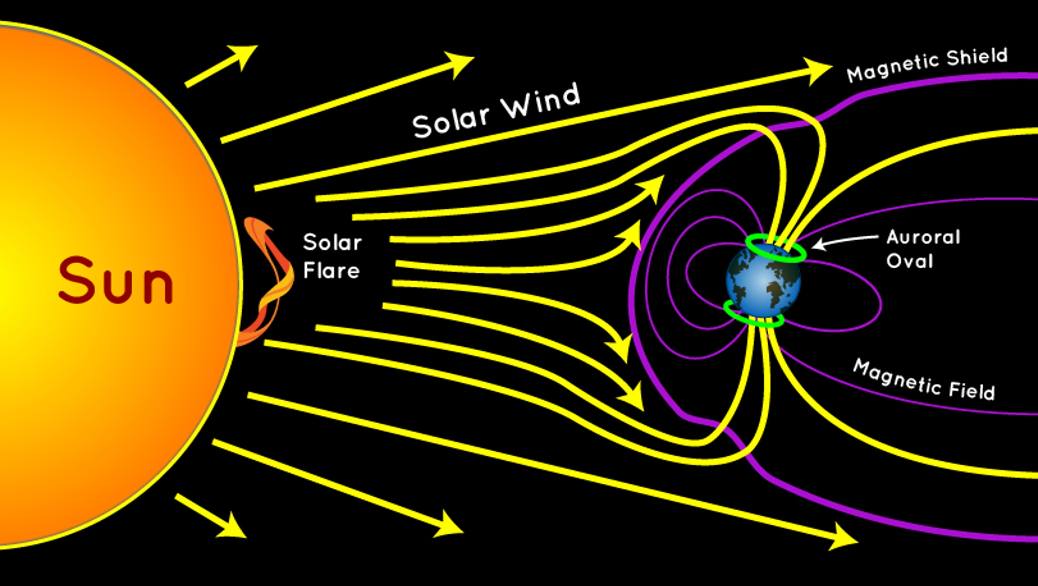
When this solar storm hits the Earth, the Earth's magnetic field can be deformed to such an extent that charged particles are accelerated toward the Earth, resulting in a magnetic field. This magnetic field interacts with the earth's conductivity, resulting in earth voltage differences. Geomagnetically induced currents (GIC) flow in the earth. To compensate for the potential differences, the currents search for the paths of the lowest resistance. Grounded transformer star points offer the currents the low-impedance high-voltage lines as a current path.
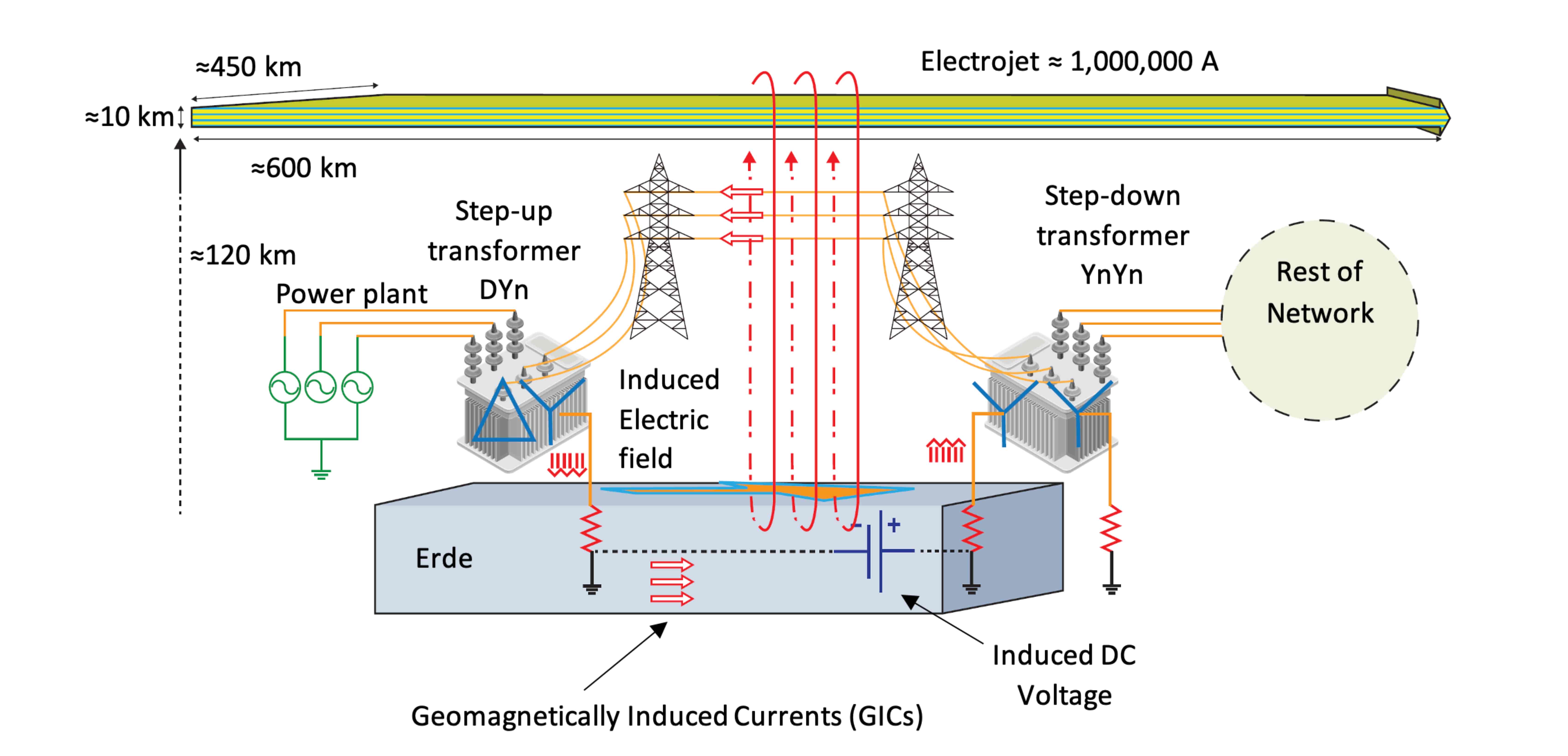
The frequencies of GICs are between 100 µHz and 8 mHz. These low frequencies are often generalized as DC currents. Even at low amplitudes, these frequency components can drive inductive components into the magnetic saturation region. In a power transformer, for example, this leads to an increase in no-load losses, vibration and noise.
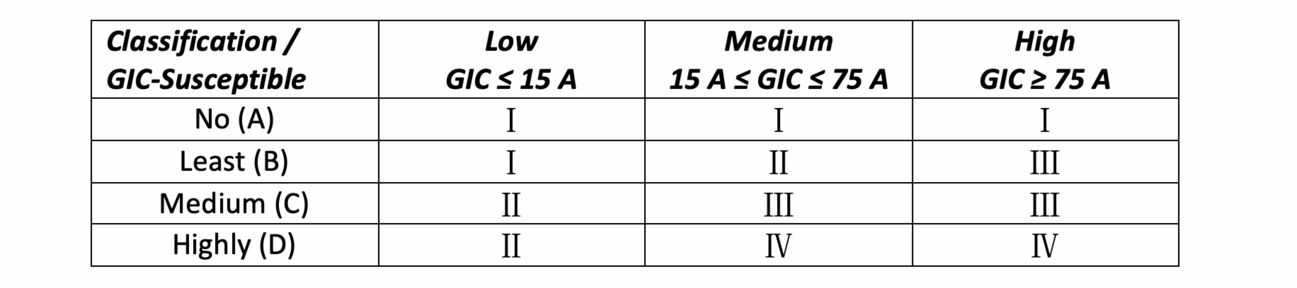
In order to ensure the safety and service lifetime of transformers even with existing GICs, a guideline was published by the IEEE in 2015 that defines different categories for the transformer equipment with regard to the GICs to be expected. /2/
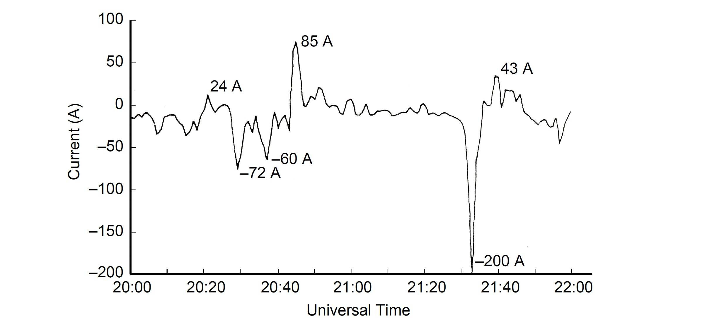
The current intensity of the GIC depends mainly on the intensity of the occurring solar storm. Directly, the position and the orientation of the overhead line as well as the earth impedances between the line ends also affect the DC amplitudes. In general, the GICs can certainly be described as strongly fluctuating. In individual cases, amplitudes of up to 100 A or more can be reached. /4/
In general, areas with high latitude lines are more often affected by GICs.
Hybrid lines
In addition to GICs, hybrid lines, where a conventional alternating current (AC) system is routed together with a high voltage direct current (HVDC) system on a common overhead line route, are also a potential source of DC currents in AC systems today. The close proximity and potential difference between AC and DC systems results in an ionic current between the two systems. Depending on the exact conductor rope arrangement and the conductivity of the air, an ion current of up to 10 mA/km results on parallel lines. /6/
DC systems with an earth connection
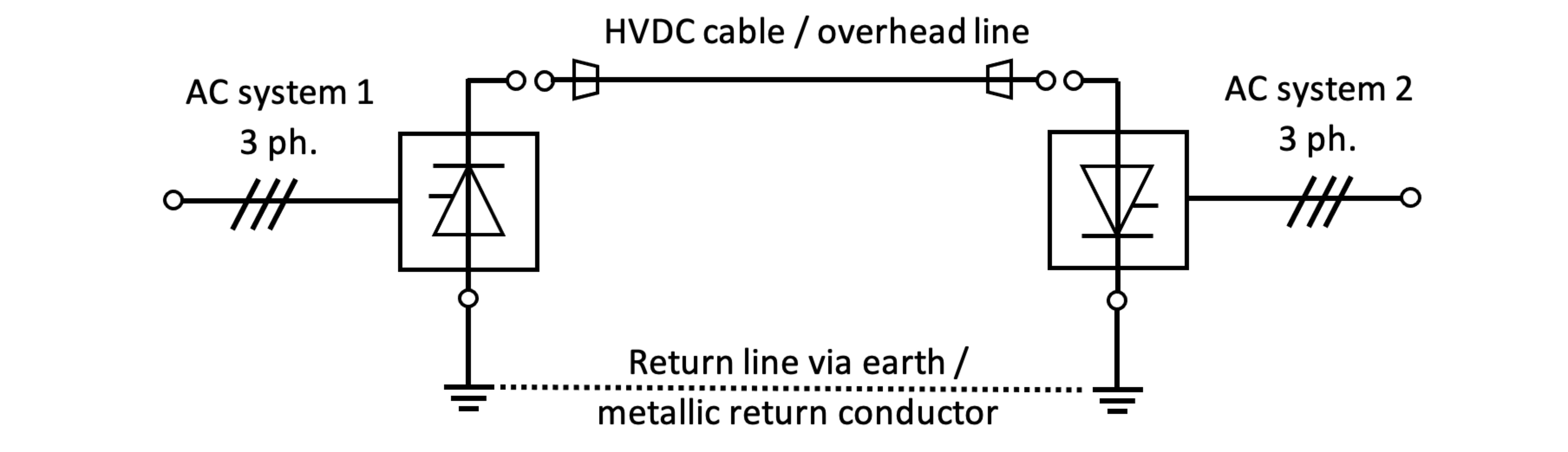
In addition to hybrid lines, DC systems with ground conductors are another potential source of unwanted DC currents. The simplest design of a DC transmission is a monopolar arrangement consisting of a high voltage DC line and a grounded electrode as return conductor. This mode of operation is especially common for older systems using submarine cables. The cost of a return conductor can be saved in this way. However, non-maritime systems have also used the ground to return the DC current. However, these installations are no longer eligible for approval. In principle, an additional metallic return conductor must be installed for monopolar direct current transmissions.
New plants are mostly designed as bipolar systems. Bipolar means that, in contrast to monopolar HVDC, two metallic conductors are used, with grounding at medium potential: one conductor that has a positive voltage with respect to the ground potential, and one conductor that has a negative voltage with respect to the ground potential, for example ±450 kV. In this case, the DC voltage between the two conductors is twice the voltage as between one conductor and ground, 900 kV in this example. Depending on the design, a metallic return conductor can also be included, which is insulated from the ground in its course. Then, in the event of a line failure, continued operation with half the voltage is possible. The bipolar version has the advantage that the magnetic field of the current in the return conductor compensates quite well for that of the supply conductor, since they are oriented in opposite directions. After several meters, the field strength is below that of the weak earth magnetic field, the more so the the closer the supply and return conductors are arranged.
The current flow in each pole is necessarily symmetrical, the unbalanced current components flowing to ground are usually less than 1-2% of the rated current. /7/
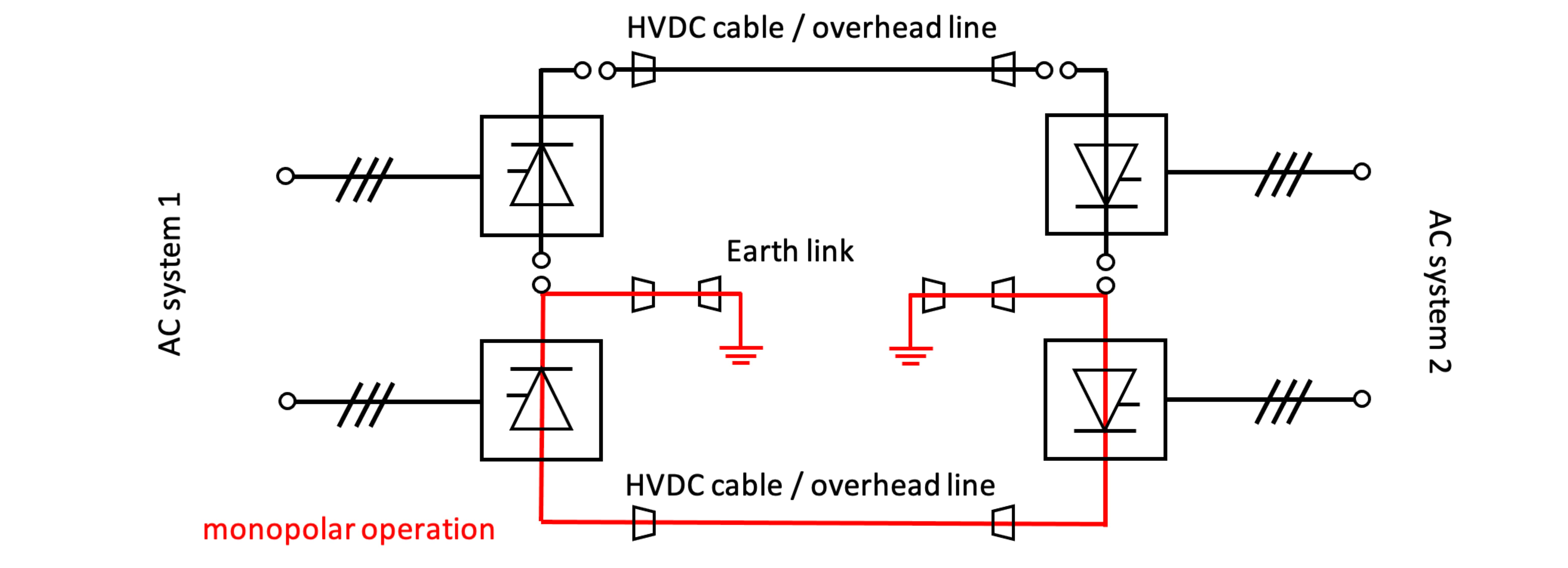
Bipolar systems can also be designed to operate as a single monopole if required. Due to a single-pole fault or maintenance work, the bipolar system in the following figure can be operated as a single pole.
In general, any DC system that uses the ground as a return conductor is a potential source of DC interference in overhead power lines. The return conductor currents can be AC systems with a grounded neutral point as a bypass to the current flow path in the ground.
DC track systems with non-insulated return conductor
In addition to HVDC systems, stray currents from railroad networks can also enter the high-voltage network via grounded transformers.
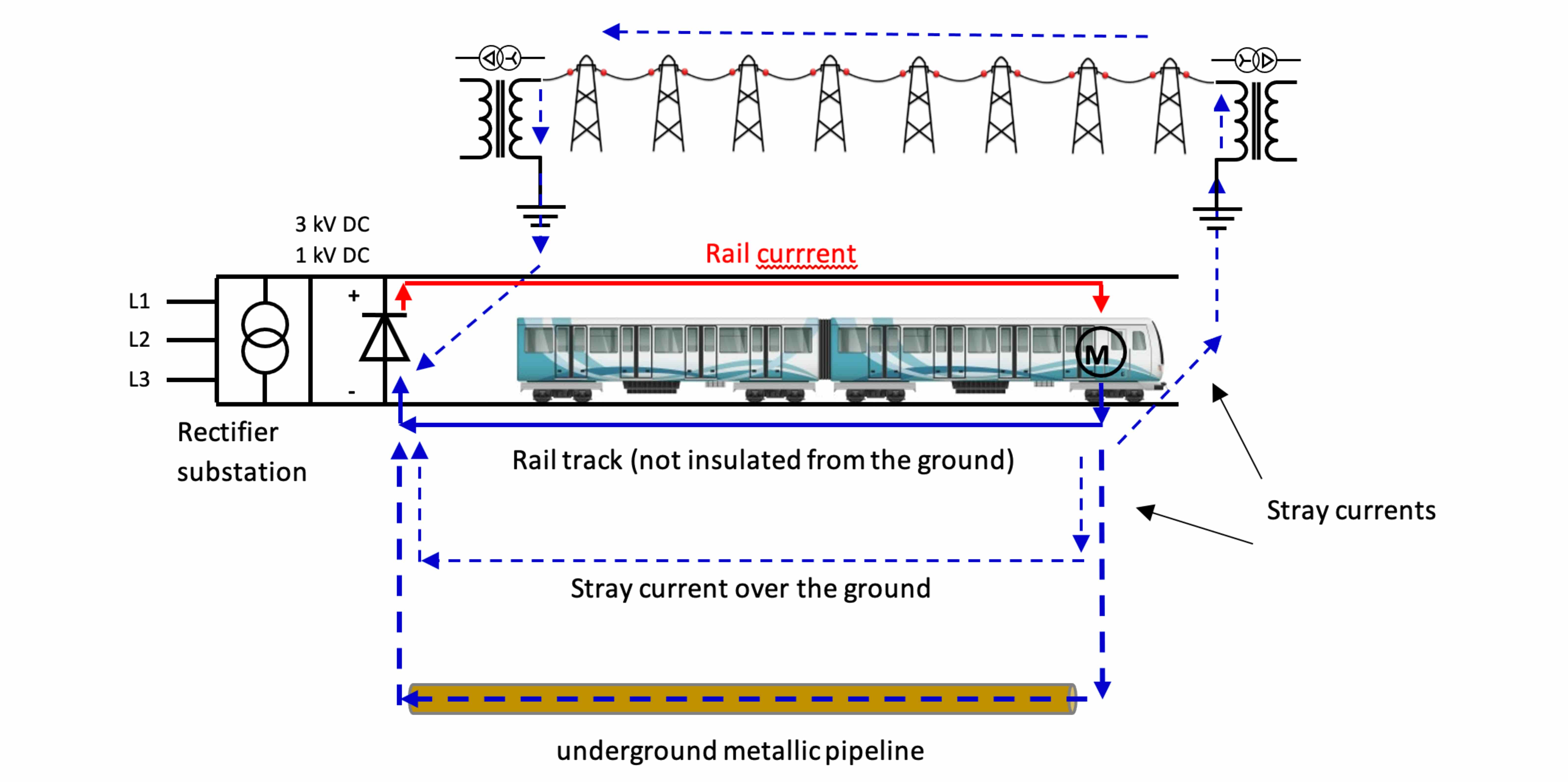
Complete insulation of the return conductors is usually not given, which means that other current paths cannot be completely excluded. The current amplitudes of the stray currents correlate with the resistances of the alternative current paths.
DC components by non-linear loads and feed-in systems
Many standardization bodies are already aware that, for example, inverters of photovoltaic systems can feed DC components into the supply network. This is mostly due to small differences in the u-i characteristics of the semiconductor components used. The German VDE-AR-N 4100 of 2019 therefore contains the following passage.
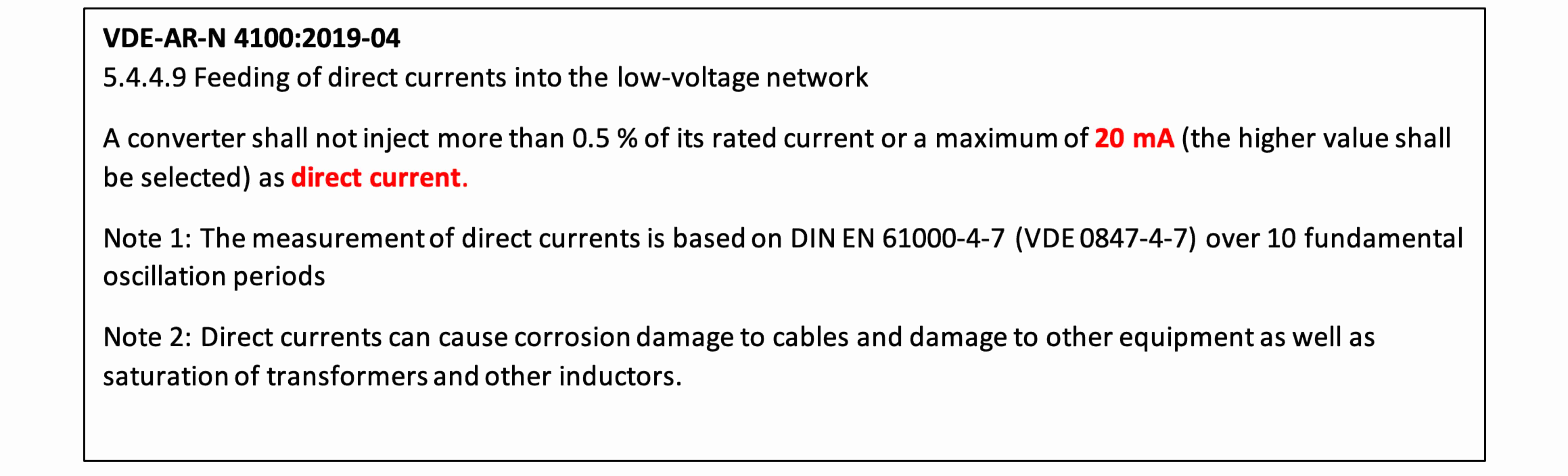
The DC component is limited to 0.5 % or a maximum of 20 mA of the rated current in accordance with this directive. Similar rules can be also found for example in the Australian standard AS4777.2, IEEE standard 1547-2003 and in the Italian standard CEI 0-21.
In a recent publication, three different converters have been investigated. The following results were determined. /8/
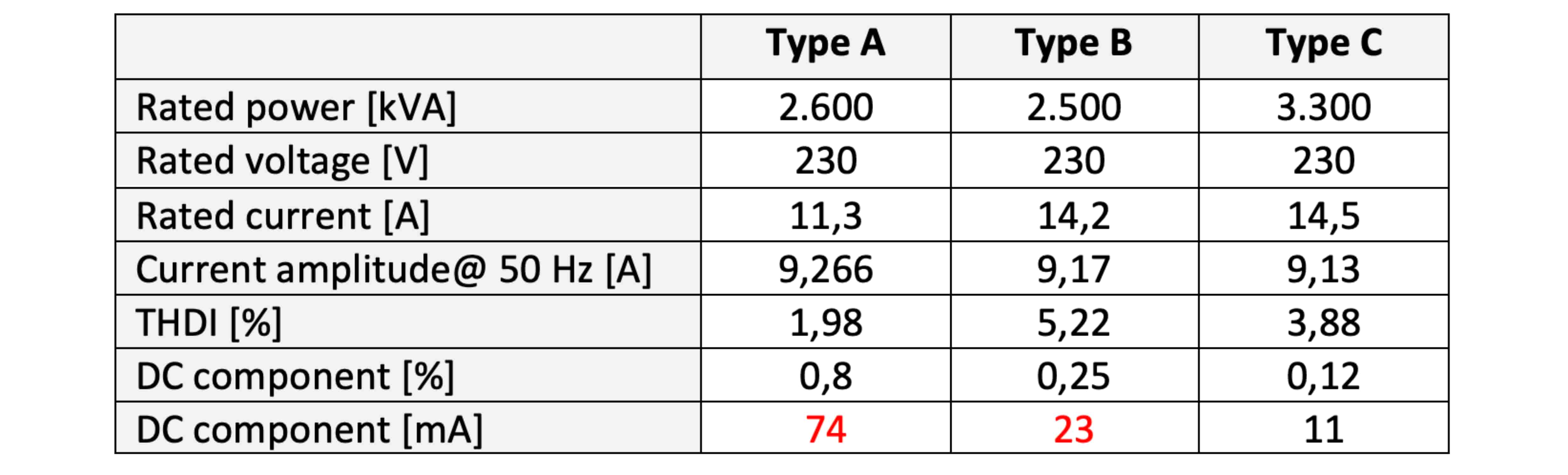
Two of the three models examined produce a DC component that is above the 20 mA limit. A control of these values in the field is usually not checked by the distribution network operator.
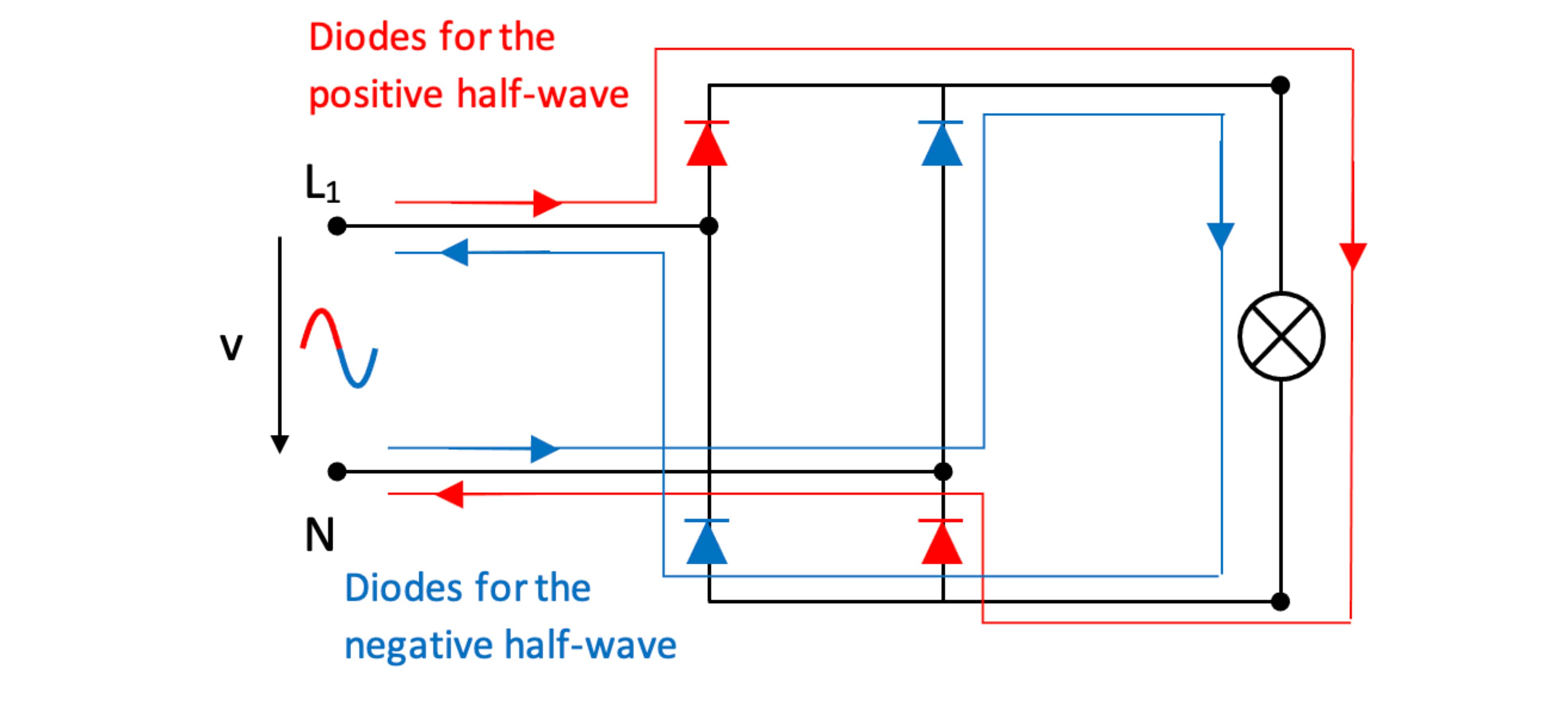
But also, every PC power supply is a potential DC source. Due to slight differences in the u-i characteristics of the diodes (red diodes unequal to blue diodes), an asymmetry of the two half-waves occurs.
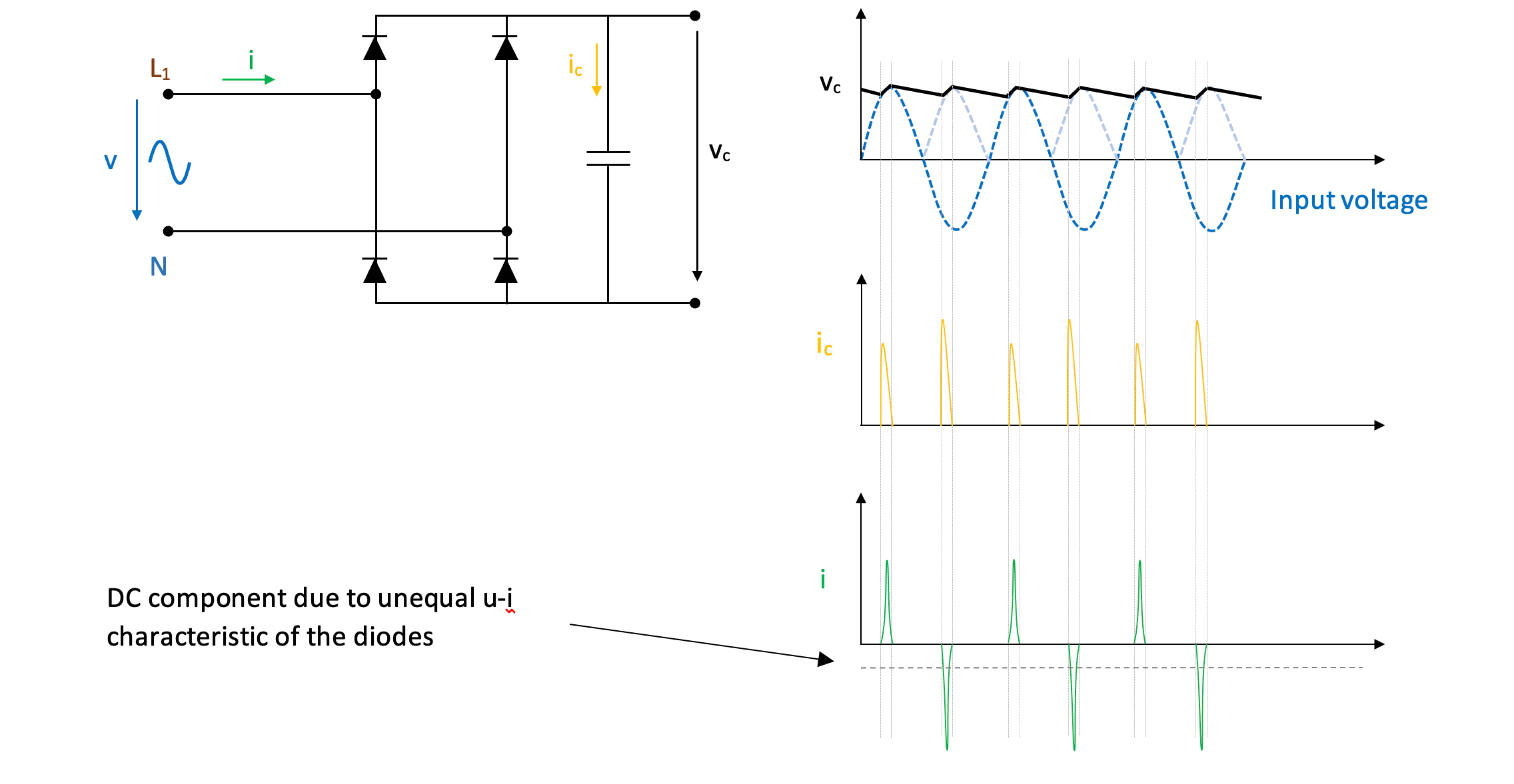
If a bridge rectifier is now implemented with slightly different diodes, the following current characteristics result.
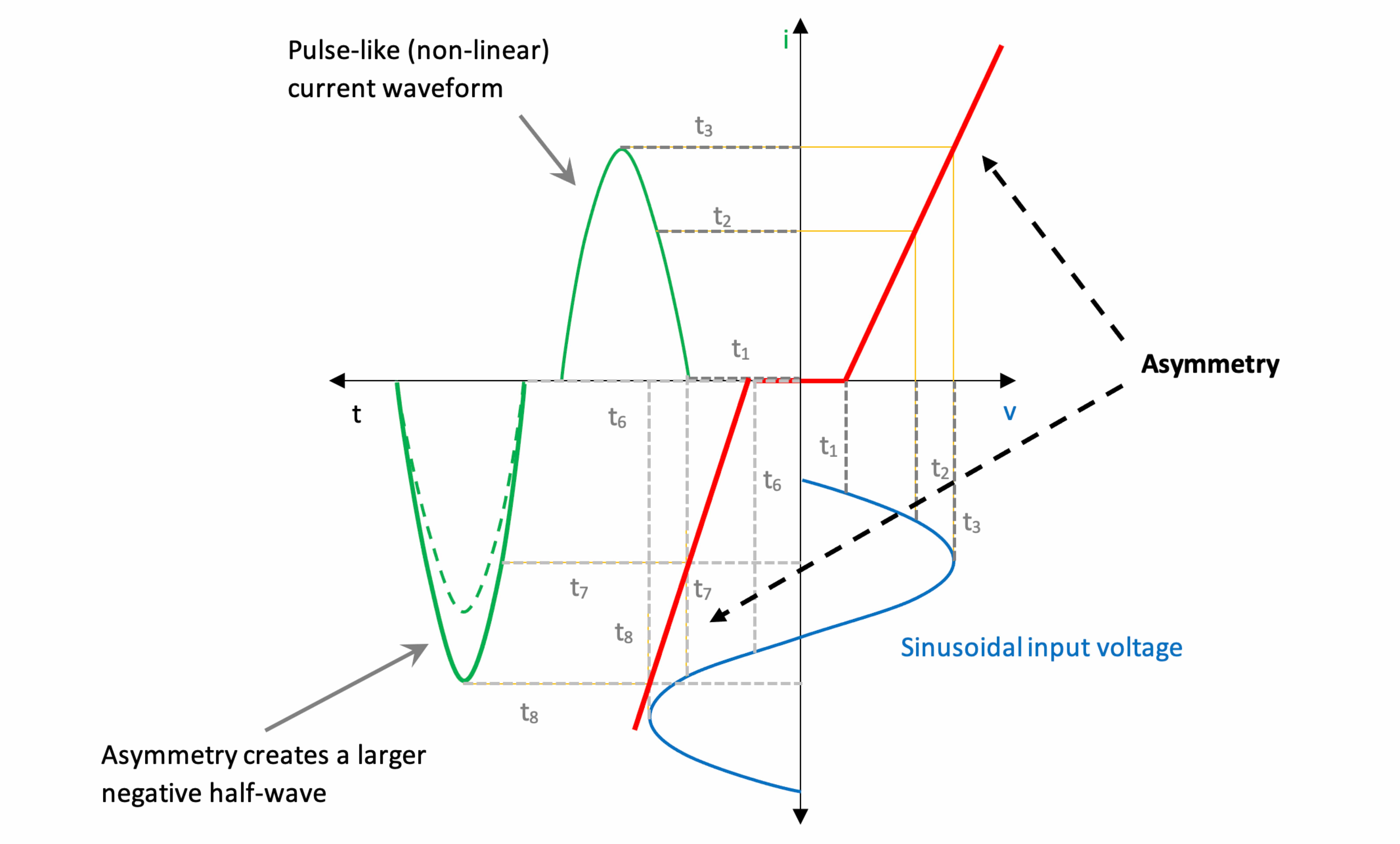
The complete u-i diagram is shown in the following figure. The negative half-wave of the current in green color is significantly larger than the positive half-wave (dashed) due to the asymmetry of the u-i characteristic curve.
These DC components have already been proven in practice /9/. Nine desktop computers and one laptop were examined for this purpose. The DC component depends on the computer's current power consumption.
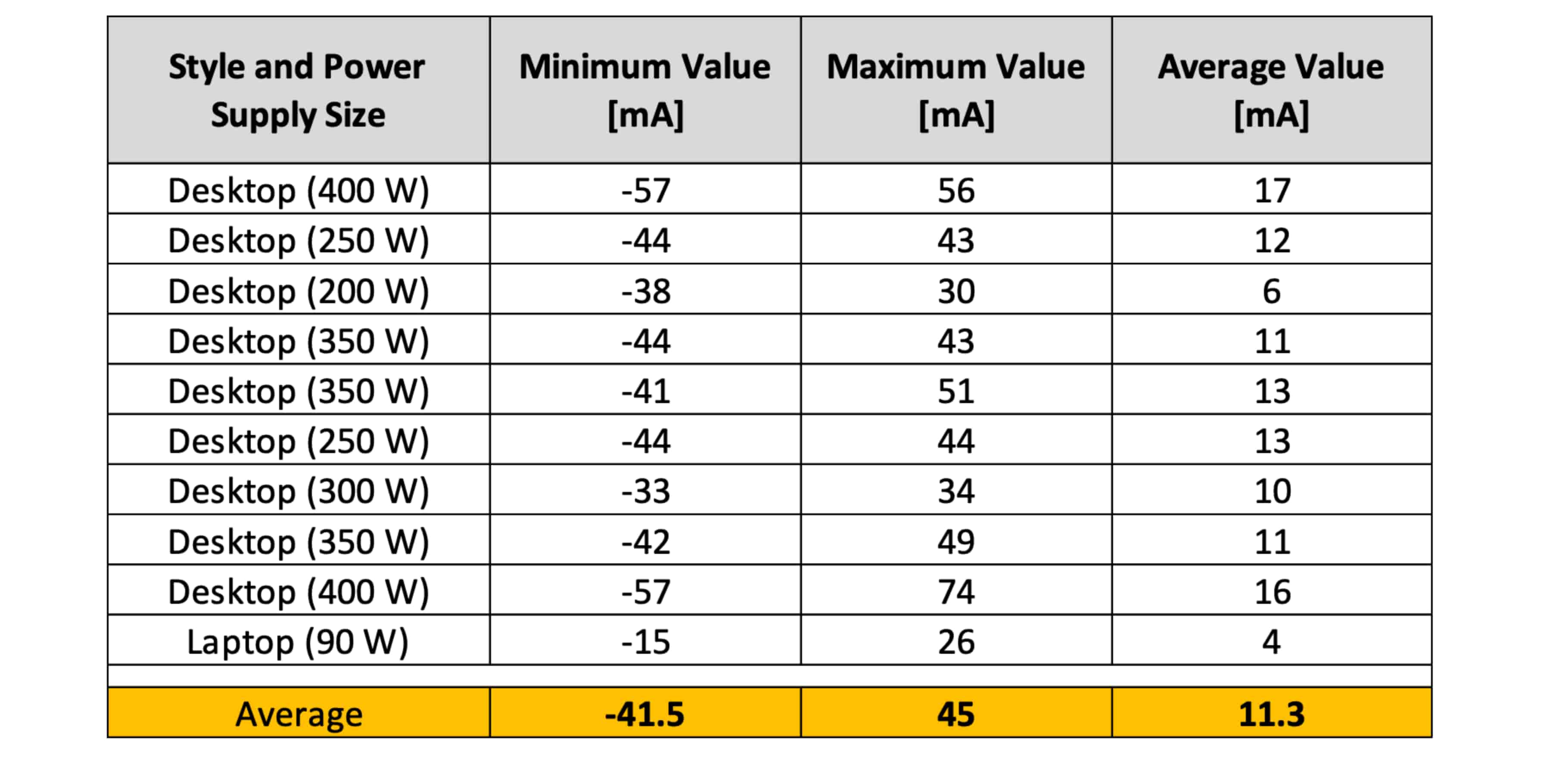
On average, one computer generated 11.3 mA. In unfavorable constellations, considerable DC components can thus be reached in office buildings.
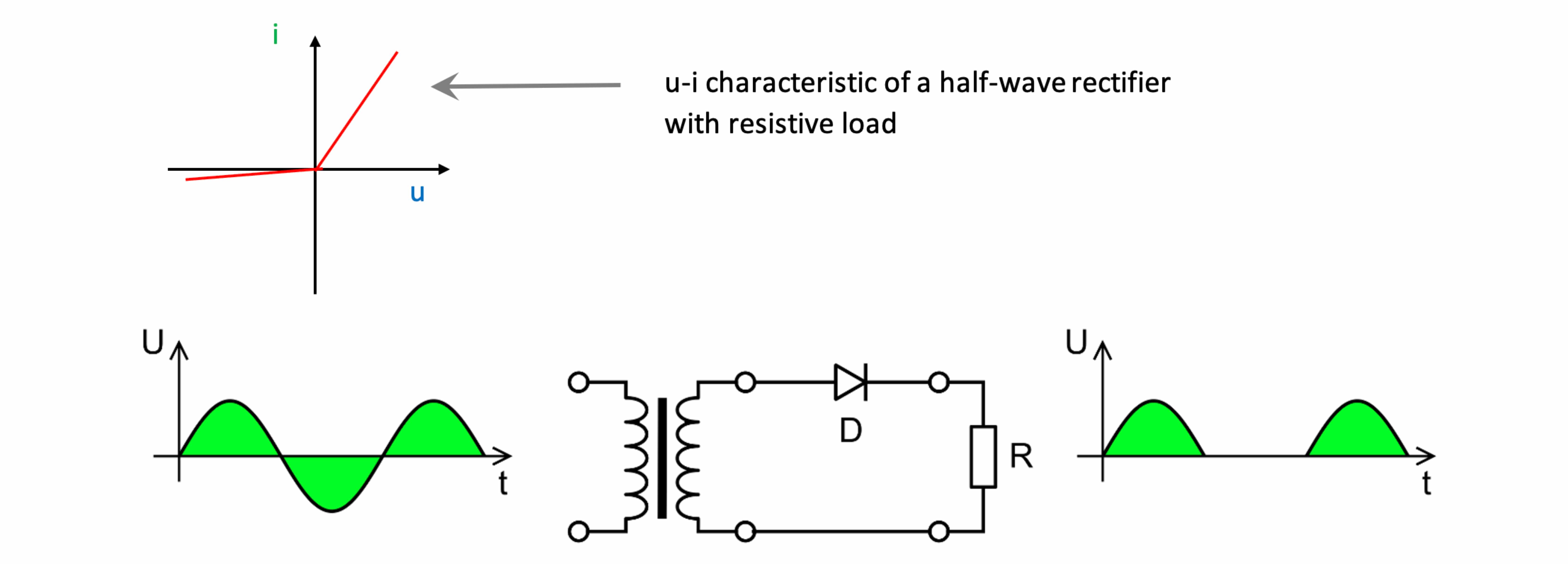
But an ordinary hair dryer as a consumer is also enough to generate a DC component. In most cases, the electronic circuit consists of a half-wave rectifier with a resistive load. This means that only the positive half-wave is used to provide energy. A current can only flow in the positive half-waves of the voltage.
Effects of the DC component on inductive current transformers
Like all transformers, the current transformer also has an iron core which is magnetized by the primary magnitude. This primary magnitude is transformed to the secondary with the desired transformation ratio. The current transformer is a transformer that is driven almost in short circuit. Thus, the current is the injected parameter and not the voltage as in power transformers. A DC component in the AC signal will magnetize the iron core, but a transformation to the secondary cannot occur due to the basic laws of physics. The partial magnetization of the core will shift the magnetic operating point of the current transformer. The magnetizing current of the iron core, which is mainly responsible for the amplitude and phase error, changes. The boundary conditions under which the accuracy of the transducer was defined have changed with a DC component. The question arises what influence even small DC components have on the accuracy of current transformers.
GICs are low-frequency components in the range between 100 µHz and 8 mHz. Despite the designation DC current, it is an oscillation. Therefore, the calculation formula that outputs the magnetic flux density in Tesla can be used.
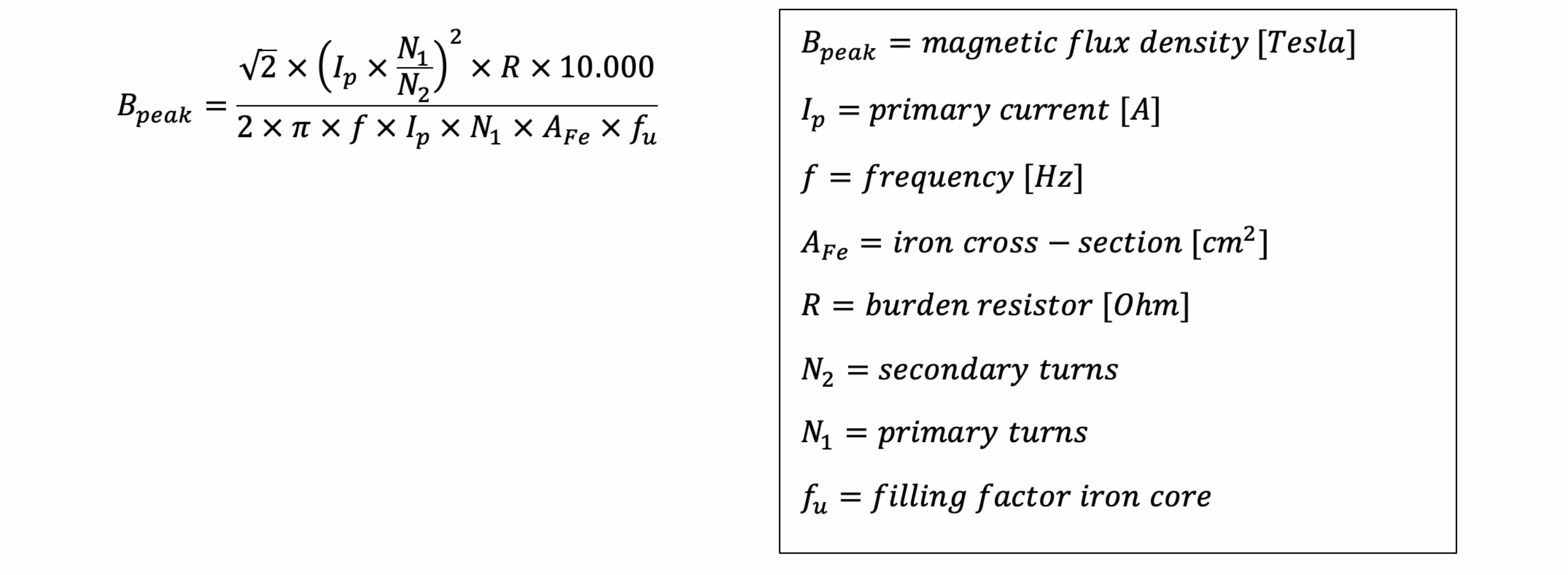
Let us now take a feedthrough current transformer for measuring tasks with the transformation ratio of 100/1 A and a load power of 5 VA. With an iron cross-section of 6 cm2 , we are at a not unusual magnetic flux density of approx. 0.4 T for Fe-Si alloys. For the rated frequency we choose 50 Hz. The saturation range of these alloys lies in a range between 1.65 and 2 Tesla.
If we now assume that in practice this current transformer is only loaded with the still permissible quarter load of 1.25 VA, this measure lowers the magnetic operating point again to approx. 0.1 T. Here, the electrical resistance parameter (R) is reduced to 1.25 Ohm. If we now calculate the magnetic operating point for a GIC of 5 mA and 0.0001 Hz alone, we obtain a remarkable 2.47 T. This means that the CT is already deep in saturation at a signal component of 5 mA and 0.0001 Hz.
The University of Stuttgart has investigated the effects of parasitic DC components on inductive current transformers /11/. While protection cores with an air gap react much more resistant to DC components, as expected, the current transformer for measurement purposes already leaves the specified class 0.2 at 100 mA DC and is at approx. -0.55 % with the amplitude error. Basically, measuring cores react more sensitively to DC components, because these transformers are often designed with an overcurrent limiting factor. This is usually 5 or 10, which means that the current transformer must saturate at the latest at 5 or 10 times the overcurrent at full load. This in turn means that the transmitted secondary current is limited. This protective measure applies primarily to the connected measuring device. Often, however, this protective method is no longer relevant, since many measuring devices use small current transformers for the current inputs themselves, which have a corresponding saturation behavior in order to protect the connected precise measuring shunt.
If the operating point of the current transformer has now been shifted by a DC component, the question arises whether the undesired magnetization can be neutralized again by standard operation.
In principle, relatively large remanences result for closed toroidal band cores. The remanence factor Kr is calculated in the standard as the quotient of the remanence flux and the saturation flux. /12/
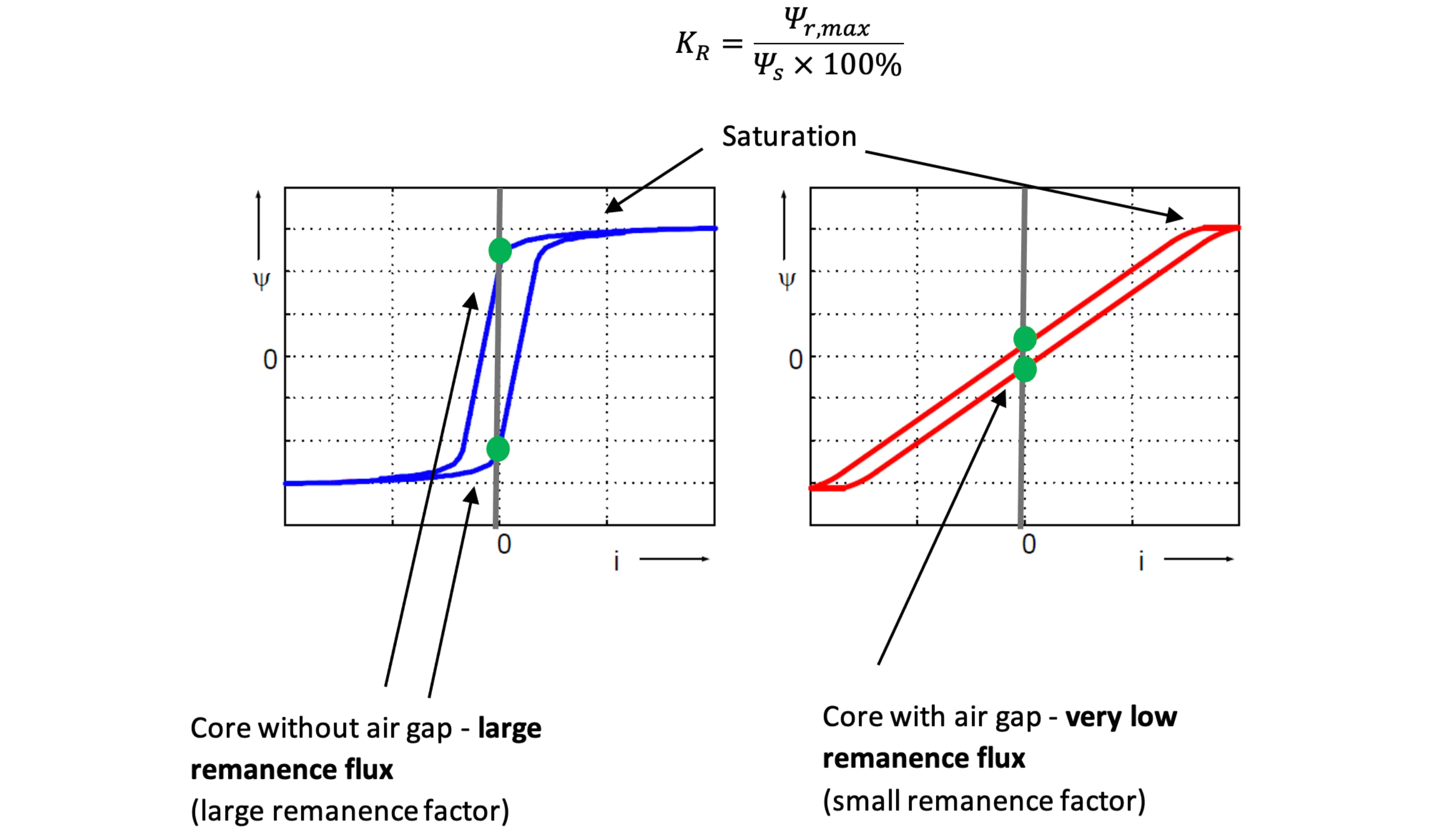
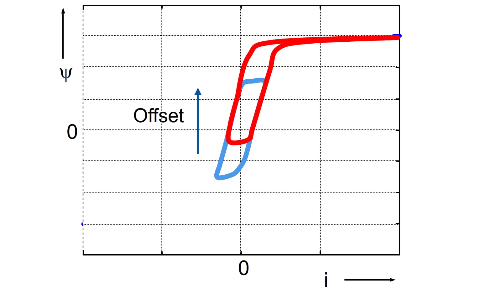
If a GIC now flows through the primary conductor, the magnetic operating point can be shifted. Instead of the blue hysteresis curve, the AC signal now passes through the red curve. Not only the accuracy suffers, but the current transformer also consumes a significantly larger magnetizing current when the saturation level is reached.
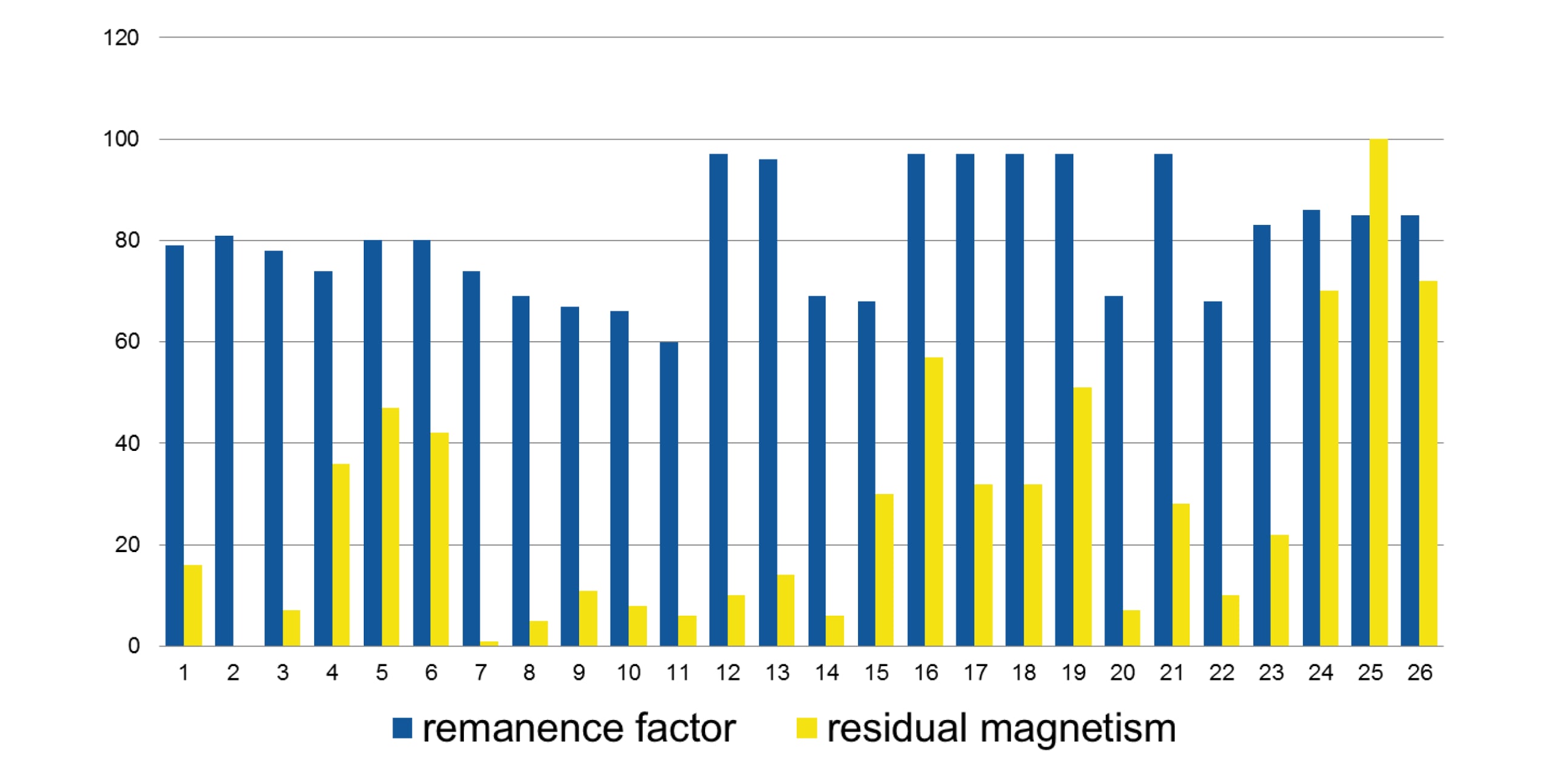
Only a part of the residual magnetization is removed in standard operation. This was already demonstrated for protection cores in 2006 /13/. Measuring cores differ mainly in the earlier entry of saturation in the event of overcurrent. In another study by Omicron, remanence factors and the residual magnetization present in the field were investigated in 26 medium-voltage current transformers /14/. It was shown that closed current transformer cores have a consistently high remanence factor greater than 60 %. The residual magnetization before measurement was between 0 % and 100 %.
DC tests are already mentioned normatively for energy meters because of the possible DC components due to non-linear loads /15/. The core material of the input current transformers used in these meters is similar to a core with an air gap in terms of the B-H characteristic. An undesired high magnetization with DC currents can thus be suppressed. However, these core materials often result in large phase errors that have to be corrected later in the meter electronics.
Zero-flux current transducers
For reference measurements in the different voltage levels and for clearing measurements above 110 kV systems, zero-flux current transformers are used for the reasons mentioned here, which can transform DC currents as well as AC currents to the secondary side with high accuracy.
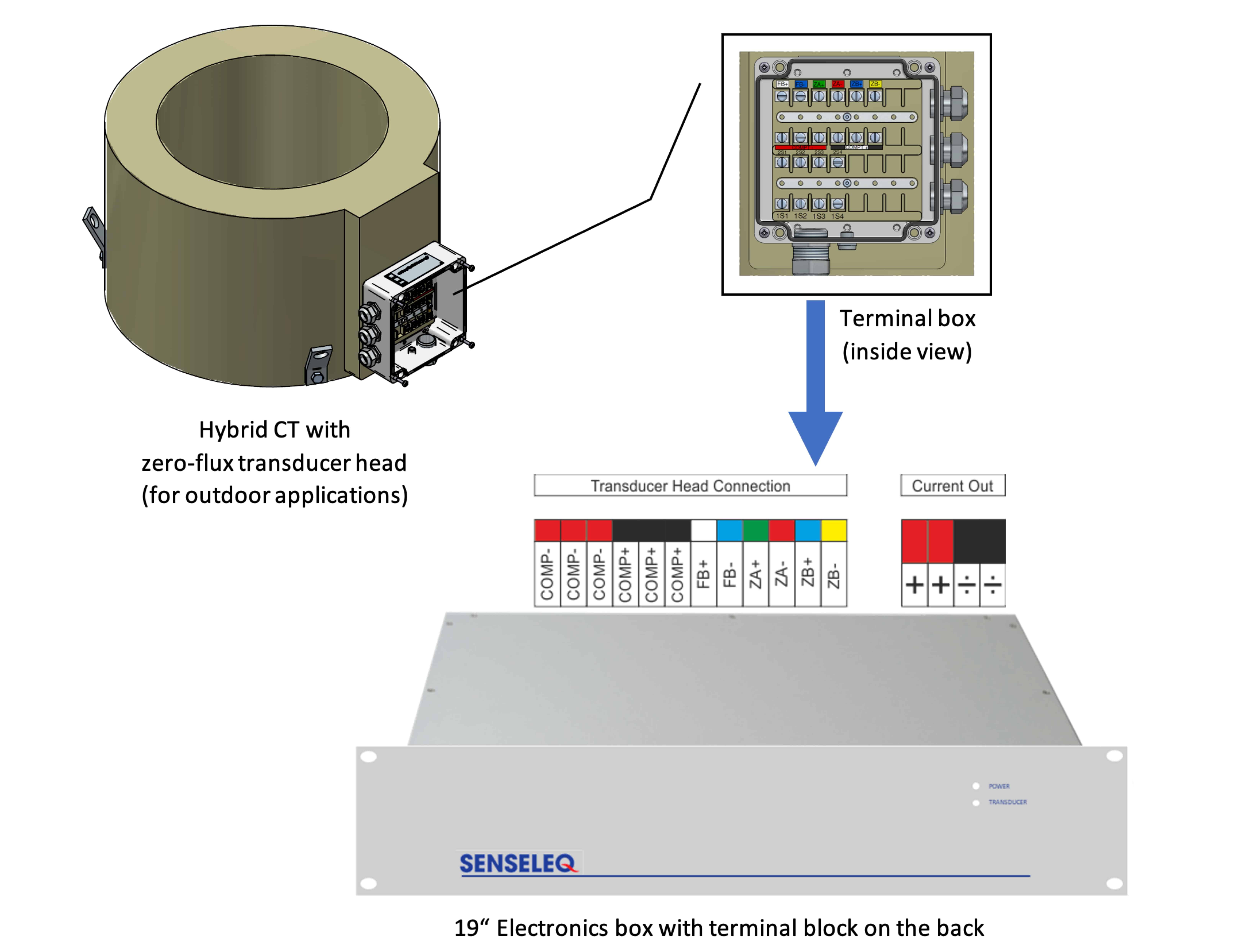
DC components and power quality parameters such as harmonics are recorded with a power quality analyzer and transmitted to the control center via a SCADA system. At the same time, the highly accurate 50 Hz values for digitization projects can be transmitted to the control room via the IEC 61850 protocol. Disturbances in protection systems and faulty measurements can thus be analyzed more easily. Dangerous DC components for inductive components can be detected at any time.
Conclusion
Measuring cores of current transformers can be significantly affected in their accuracy even by small parasitic DC currents. Potential DC sources can be found at all voltage levels. As in the laboratory, it may be useful to use DCCTs with the zero-flux principle to maintain complete control over the networks. It has already become clear in recent years that laboratory measurement technology is also taking its place in the grid infrastructure with a time lag. For current measurements in the laboratory, zero-flux current transformers are used in most cases in order to be able to measure subharmonics and DC components as well. At the same time, current harmonics can be reliably measured down to the megahertz range. The accuracy is almost perfect.
Credits:
/1/ https://scijinks.gov/aurora/
/2/ IEEE C57.163-2015
/3/ IEEE C57.163-2015 IEEE Guide for Establishing Power Transformer Capability while under Geomagnetic Disturbances.
/4/ D. A. Vernon, „Electric and Magnetic Fields at the Earth's Surface Due to Auroral Currents,“ IEEE Transactions on Power Apparatus and Systems, pp. 578-584, April 1970.
/5/ J. Elovaara, P. Lindblad, A. Viljanen, T. Mäkinen, R. Pirjola, S. Larsson, and B. Kielén, “Geomagnetically Induced Currents in the Nordic Power System and Their Effects on Equipment, Control, Protection and Operation,” paper 36-301 of the proceedings of the CIGRE 1992 Session, Paris, France, 1992.
/6/ B. Rusek, „Ohmic coupling between AC and DC circuits on hybrid lines,“ Cigré – Symposium Auckland, 2013
/7/ Hochspannungsgleichstromübertragung – Eigenschaften des Übertragungsmediums Freileitung
/8/ Investigation of the Effects of DC Current Injected by Transformer-Less PV Inverters on Distribution Transformers Md. Ashib Rahman , Member, IEEE, Md. Rabiul Islam , Senior Member, IEEE, A. M. Mahfuz-Ur-Rahman , Member, IEEE, Kashem M. Muttaqi , Senior Member, IEEE, and Danny Sutanto , Senior Member, IEEE
/9/ The Effect of DC Current on Power Transformers A dissertation submitted by Ashley Karl Zeimer
/10/ Von Wdwd - Eigenes Werk, CC BY 3.0
/12/ IEC 61869-2
/13/ Dickert, J.; Luxemburger, R.; Schegner, P.: Investigation on the behavior of the remanence level of protective current transformers. 2006
/14/ Dr. Michael Freiburg / Rainer Luxenburger, OMICRON - Remanenz bei Stromwandlern und Auswirkung auf den Schutz
/15/ DC Tolerance Test according to IEC 62053-21, -23


