


Welcome dear friends of protection, control and electrical engineering. In our new technical article by A. Eberle GmbH & Co. KG we learn more about the parallel operation of step transformers. Here we go!
Parallel operation of step transformers
The rule of thumb that with parallel operation of transformers the ratio of the rated outputs should not exceed the value 1 : 2 (in accordance with DIN VDE 0532), can serve as a rough guide only, because the actual criteria in this rule are not directly visible. In addition, the permissible ratio also depends on the state of the art, because in the last few decades the limit has still been considered to be 1 : 3. Overall, too much attention is attached to this rule, to which a certain arbitrariness adheres.
A safer and more parallel operation of transformers is guaranteed only if their performance, i.e. whose rated outputs can be exploited fully and without overloading an individual transformer. There are two conditions to be met for this:
🌐 Equality in value, frequency and angle of the voltages because with inequality in these values a transient current flows in the parallel transformer windings.
🌐 Equality of the relative short-circuit impedances of the transformers (magnitude and angle), so the proportion of the network load for each transformer is proportional to its rated output.
The transformers' primary side must therefore be at the same voltage, and the voltages on the secondary side must each have the same value and the same angle. For the characteristics of transformers this means:
🌐 the same switching group characteristics
🌐 the same transfer ratios
🌐 the same relative short-circuit impedances (value ∆uk =<10 %)
For voltage regulation with parallel operating transformers no further claims are made.
The rated output, the most important characteristic of the transformer, has superficially in connection with the parallel operation no importance. However, taking into account economic considerations, according to the "laws of growth" of the transformers, for a given power rating there is inevitably a certain value for the relative short-circuit impedance and the relative magnetization current. Thus, there is ultimately a relationship between the rated output and the values of the two variables. The quantitative relationships, however, change with the value of the rated output (see table).
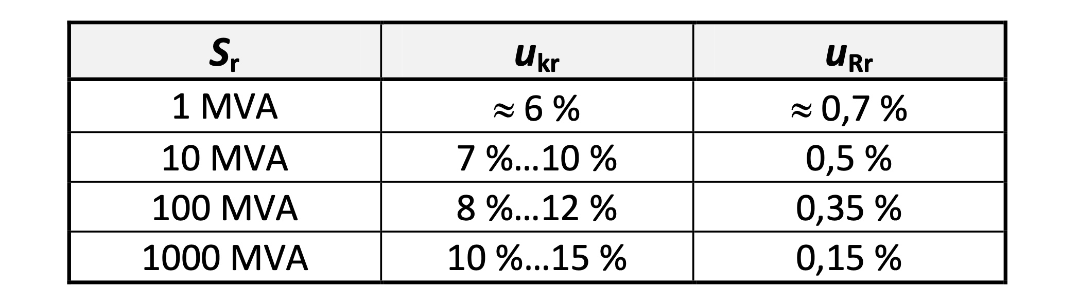
The maximum allowable differences between the values of the short-circuit impedance and the magnetizing current in parallel operating transformers depend on the respective still acceptable negative effects that are caused by these differences. Further, also the maximum load factor S/Sr of the transformers, because with a relatively small degree of utilization the negative impacts can be mitigated.
These relationships and the actual values of the relevant variables are the basis of the rule of thumb for the maximum permissible ratio of rated outputs for the parallel operation of transformers.
Justification of the requirements
In the following sections, the essential relationships for two parallel operated transformers for the simplified equivalent circuit are illustrated. Although a difference in the relative magnetization currents caused on the primary side causes different voltage drops and therefore different secondary off-load voltages, because of the relatively small value of the magnetizing current, especially for transformers with a larger rated output, this influencing variable is ignored in further considerations.
To ensure proper parallel operation, it is essential that the network load is distributed in proportion to the rated outputs of the transformers.
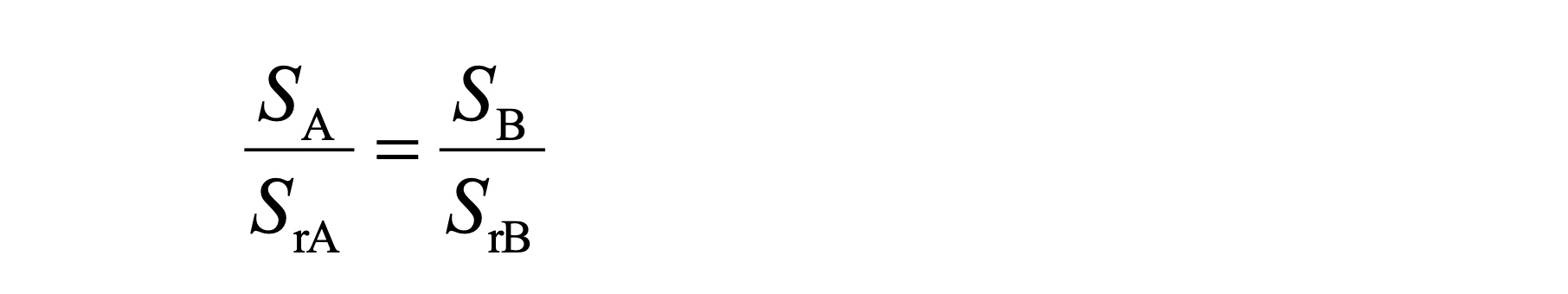
The condition is satisfied if the ratio of the short-circuit impedances is the same as the inverse ratio of the rated output and the off-load voltages (ratios) of the transformers are the same so that no circulating current flows. Because of the relationship between the values of the short-circuit impedance and the rated output, the following applies:
If two transformers are operated at one busbar, the voltage vectors of the two output voltages have the same value and angle. Ignoring the impedance of the connection lines between transformer T_A and transformer T_B , the following applies for the voltage drop caused by the load current at the short-circuit impedances of both transformers

This correlation applies for every type of load; also at different values of u_kr and φ_kr, as well as for any values of ∆U_0 = U_A0 – U_B0 (all values complex).
Ratio of load currents
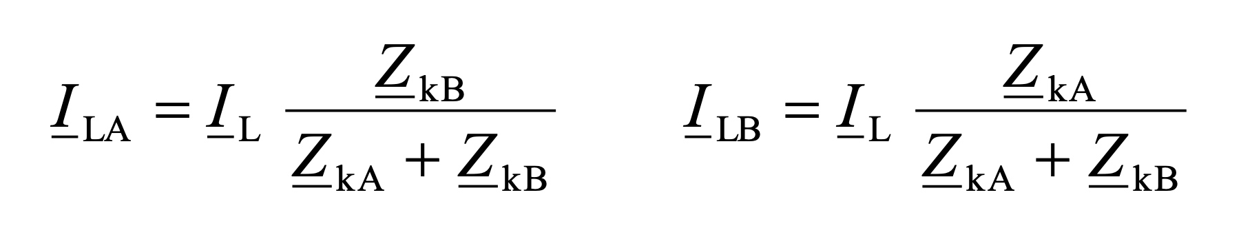
For the complex values of one phase the following relations thus result

With φ_krB = φ_krA these relationships also apply for the values (effective values) of the load current and the short- circuit impedances or for the relative short-circuit voltages and power outputs of the transformers.

There are thus with u_krB = u_krA and φ_krB = φ_krA stable relationships between the values of the load currents, the short-circuit impedance and the rated outputs.
The total load current I_L on the transformers T_A and T_B is divided according to the following equation. That also applies to the apparent powers S_A and S_B.
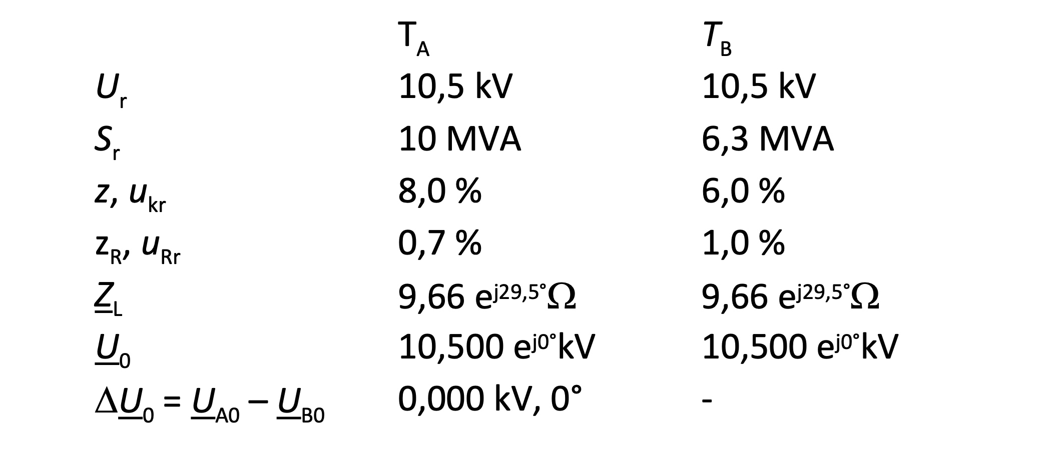
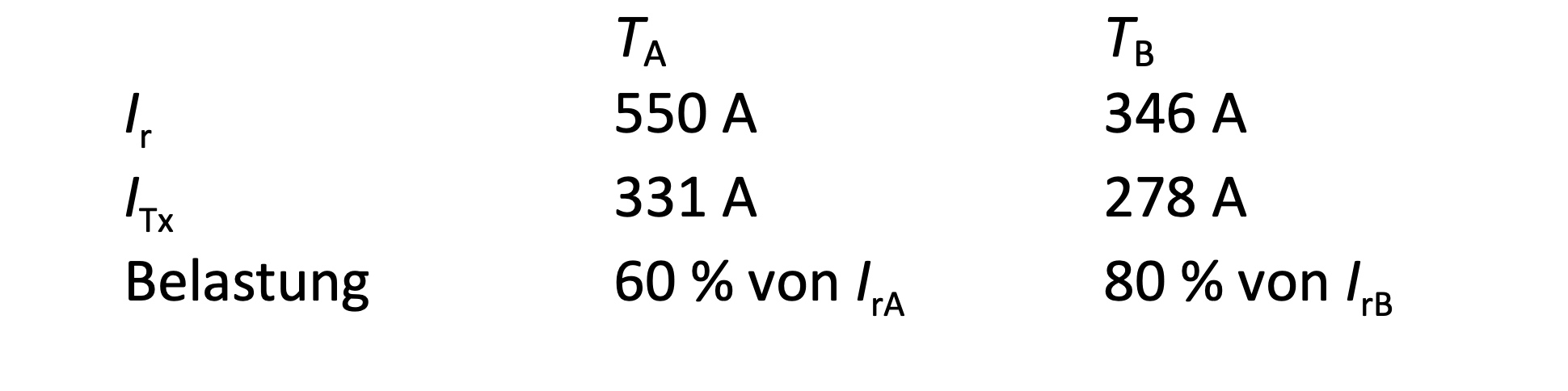
Example 1: How big is the difference of relative loading of the transformers with the given data?
Permissible difference in the short-circuit impedances
With unequal relative short-circuit impedances, transformer T_x with the smaller relative short-circuit impedance takes the relatively larger proportion of the load current I_Lx . With a high level of utilization, an overload can occur in one of these transformers so that the entire actual available apparent power with unequal relative short-circuit impedances is less than the sum of the two power of rated outputs.
Superposition of load current and circulating current
A disproportional load distribution will be strengthened by a transient current I_cir (circulating current, reactive load-independent current). The circulating current is superimposed on the load current that is supplied in the network, where the direction of the circulating current is determined by the sign of the difference U_A0 – U_B0 of the off-load voltages. With U_A0 > U_B0 for the currents I_TA and I_TB flowing in the transformers T_A and T_B, the following applies:

For U_A < U_B the sign of I_cir is reversed. Due to the respective opposite direction of the circulating current in the transformers, the load in one is increased by the circulating current and that of the other transformer is reduced. For the load current IL

Example 2: How big is the change in the relative load on the transformers?
Given data as in example 1, but
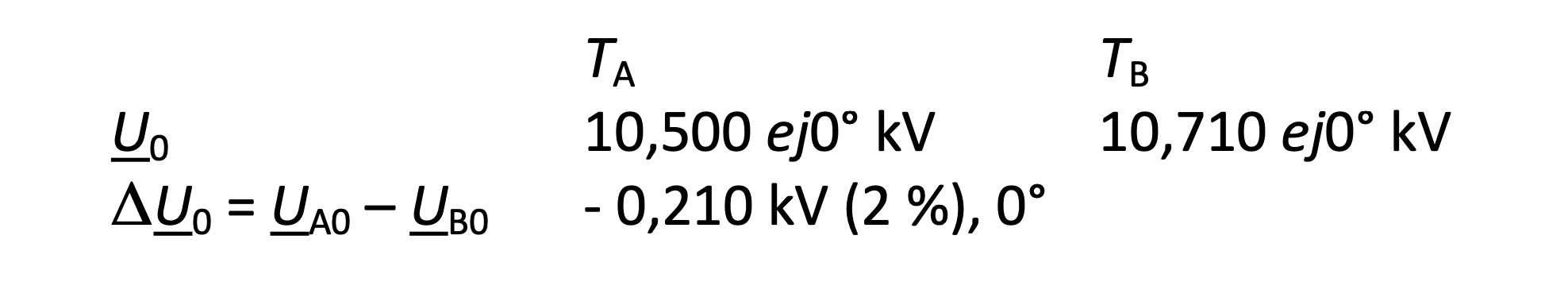
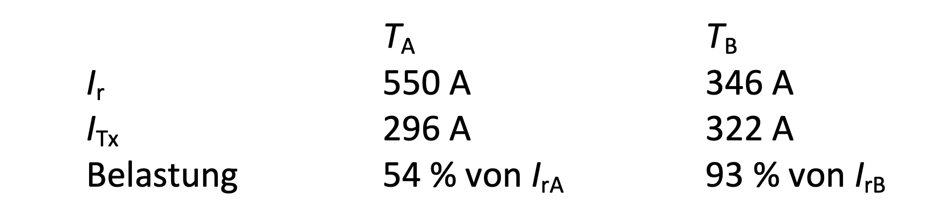
The relative load of transformer T_B increases from 80 % to 93 %. The relative load of transformer T_A decreases from 60 % to 54 %.
Note
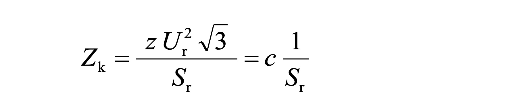
The short circuit impedance and the short-circuit voltage are normally given in a relevant form as a percentage. The benchmark values are preferably U_r^2 / S_r and U_r. To indicate this, these values are identified as "related" or "relative" sizes with the small letter z and u_kr.
For the short-circuit impedance Z, the following applies:

Author: Helmut Karger
PS .: The EXCEL programs used for the examples can be downloaded at: www.a-eberle.de (Download Center)
Kind regards
Your EEA-Team


