


Welcome dear friends of protection, control and electrical engineering. In today's technical article, Roland Bürger (Senseleq B.V.) and Dr. Thomas Heid (CONDIS SA) show us exciting technical insights and future trends in measured value acquisition in high and extra-high voltage.
Enjoy reading, we hand over.
Billing measurements in high and extra-high voltage network considering the new frequency classes according to IEC 61869-1 ED2 (AFDIS)
Internationally, it is not easy to specify the range of high voltage exactly. The boundary between medium and high voltage is between 30 kV and 100 kV, depending on local and historical conditions. In the current version of EN 50160 from 2020, the voltage levels are defined as follows.
medium voltage: voltage, whose nominal RMS value is 1 kV < Un ≤ 36 kV
high voltage: voltage, whose nominal RMS value is 36 kV < Un ≤ 150 kV
Voltage levels above 150 kV are thus assigned to extra-high voltage. The connection of generation plants such as large wind farms, conventional power plants, industrial parks and some large electricity consumers such as aluminum smelters are connected directly to the high or extra-high voltage grid. Accordingly, billing measurement often takes place here as well. In many countries, there are precise regulations regarding which technologies must be used for an official clearing measurement between two contracting parties.
Legal boundary conditions for billing measurement in Germany
In Germany, inductive current transformers are generally provided for current measurement, which must have an output signal of 1 or 5 A1. For voltage measurement, inductive voltage transformers and capacitive voltage transformers have to be used.2 The capacitive voltage transformer consists of a capacitive divider, the high-voltage capacitor C1 and the intermediate voltage capacitor C2. A medium voltage transformer is in parallel with C2 and in series with a choke coil.
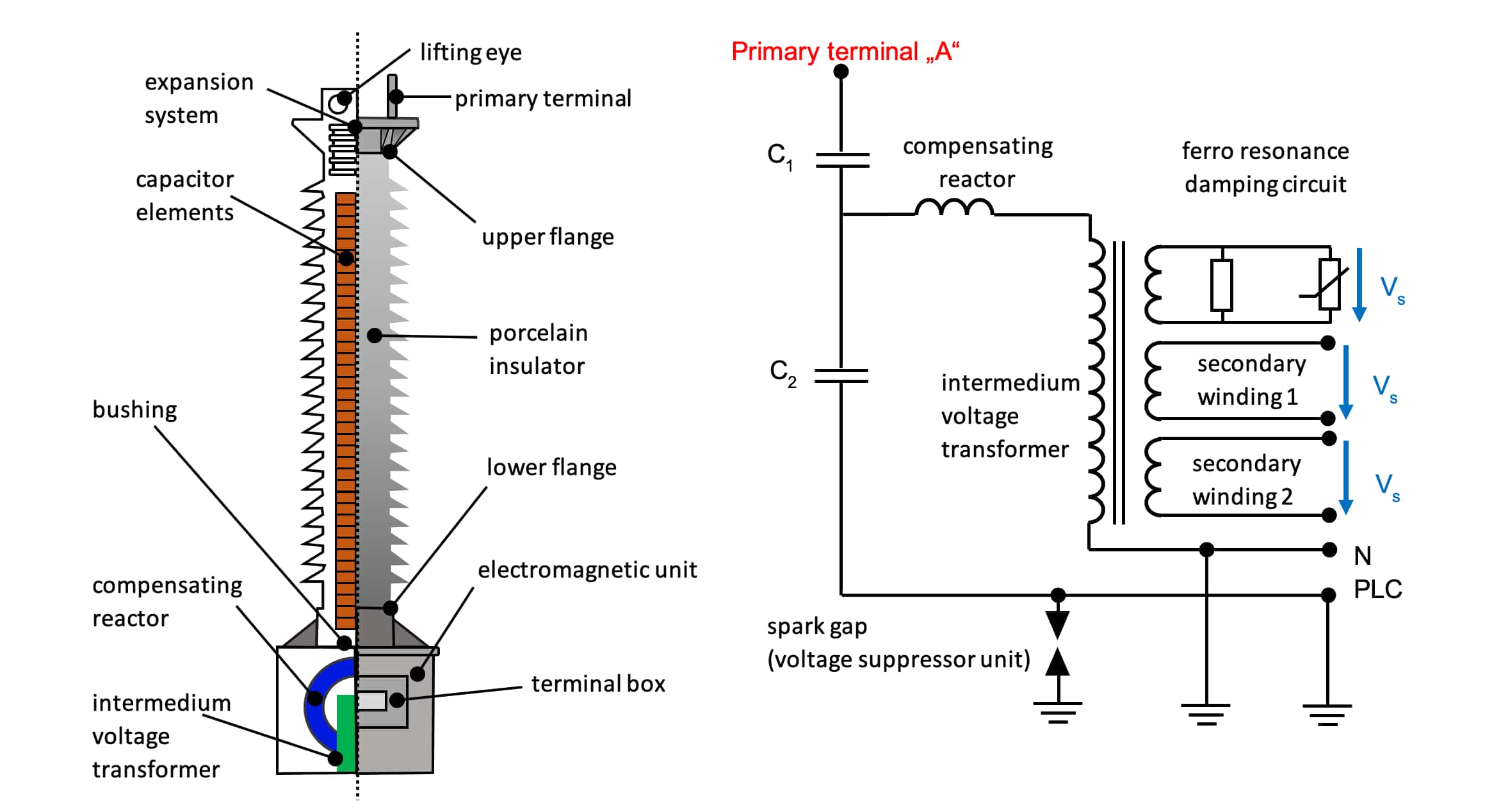
The compensation reactor is dimensioned so that the inductance is in resonance with the capacitance of the divider. The permissible output signals for voltage transformers are regulated in the PTB test rules for instrument transformers and are as follows:
100 V; 110 V; 100/√3 V; 110/√3 V; 2 x 100/√3 V; 2 x 110/√3 V; 200/√3 V; 220/√3 V und 2 x 200/√3 V
Free choice of measuring equipment from Um = 123 kV
In the current Measuring and Calibration Directive (MessEV)3, an important note can be found on page 8 of 76 under § 5 with the heading "Uses excluded from the scope of application".
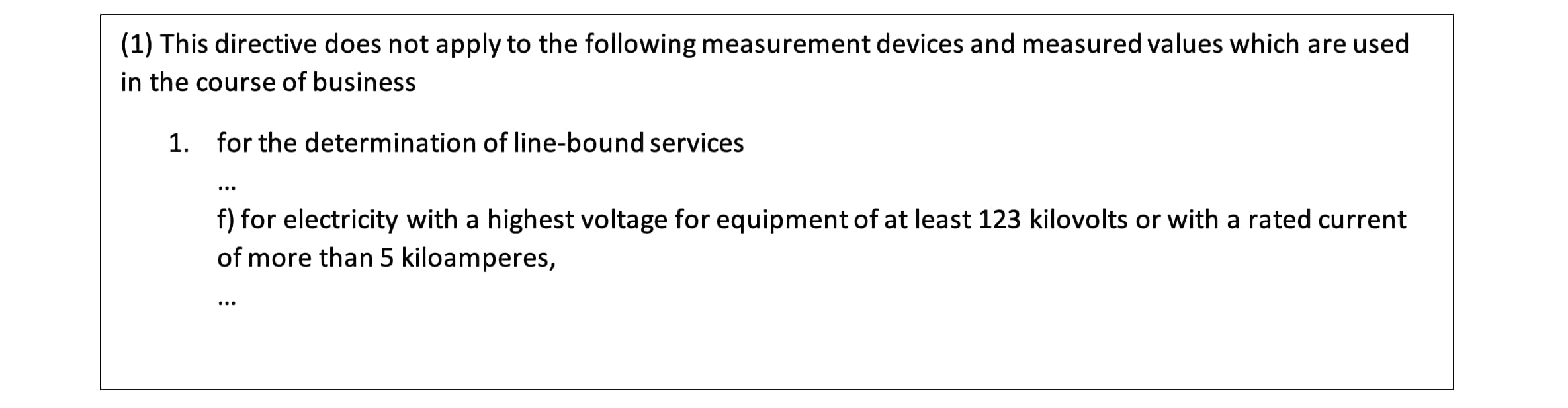
The highest voltage for equipment is designated Um in IEC 61869-1 and is labeled with Um in IEC 61869-1 and is found on every rating plate of a voltage transformer as the first value in the rated insulation level of the primary connections for instrument transformers.
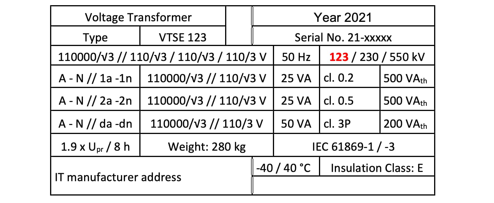
In this case, the nominal line voltage is 110 kV and correlates with the highest voltage for equipment (Um) 123 kV according to IEC 60038. Thus, in this example, the measuring equipment can be freely selected between the contracting parties in accordance with the MessEV. The reason for this procedure on the part of the authorities is that in the range above 123 kV or 5 kA nominal current, the qualification of the contracting parties is sufficient in any case to realize a professional billing measurement. In the voltage levels below that, the Measurement and Verification Ordinance can be interpreted as consumer protection. The directive ensures that the defined minimum standard is met without the contract partners having to negotiate the boundary conditions.
Actual instrument transformer status in high and extra-high voltage networks
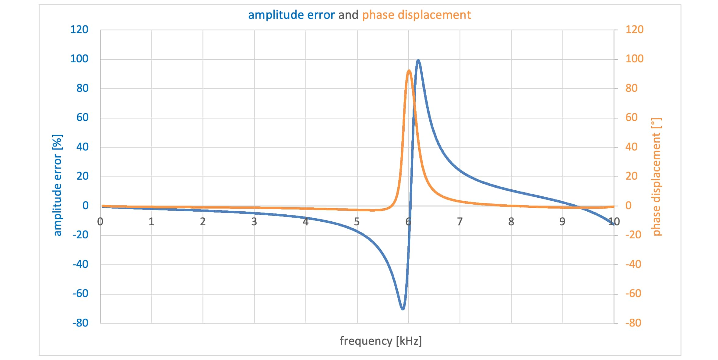
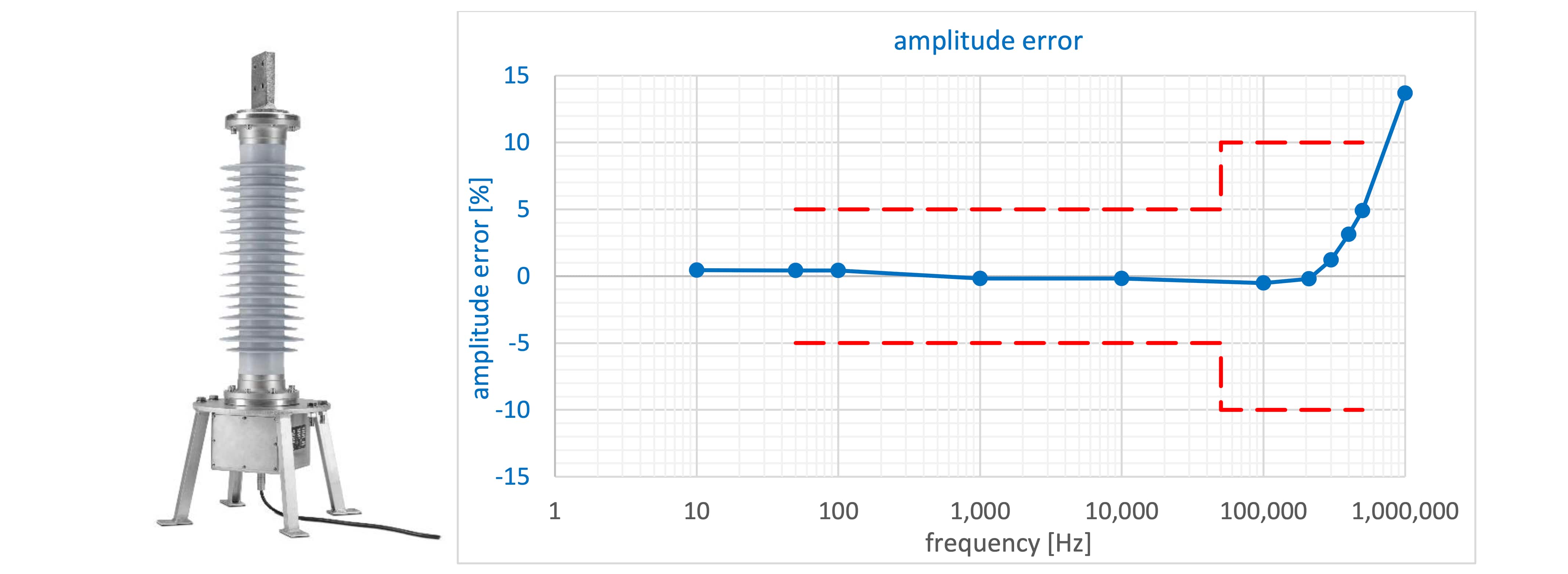
Despite this flexibility of the contracting parties, inductive voltage transformers have been installed in the majority of cases for billing measurements in the ENTSO-E4 area. Defects in these devices usually lead to a total breakdown, so that inaccuracies in the measurement over a longer period of time are unlikely. Capacitive voltage transformers are avoided for this reason, as individual capacitors can be broken down without affecting operational safety. Amplitude and phase errors can deteriorate without being noticed, so that the specified accuracy class is no longer met. This scenario may well result in a major financial loss for a contracting party over a longer period of time. A special technical feature of the capacitive voltage transformer is that the device is operated in resonance at nominal frequency. The bandwidth of these capacitive high-voltage transformers can therefore be classified as very low. In 2012, an article was already published in the etz5 regarding the frequency behavior of transformers. In addition to inductive voltage transformers, a capacitive high-voltage voltage transformer was also measured.
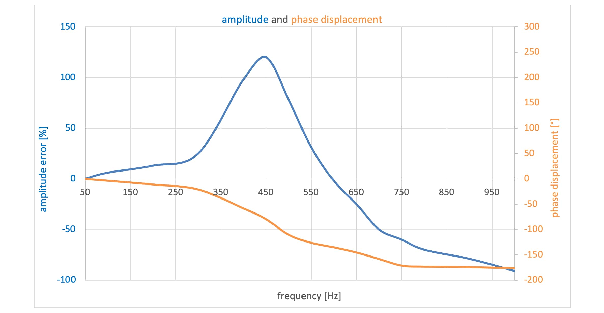
Already at approx. 450 Hz, a harmonic amplitude could be amplified by a factor of 2.2 (see Figure 4). Amplitude errors of approx. -75 % have also been measured below 1000 Hz in other devices.6
For inductive voltage transformers, an overview has been prepared by the international technical-scientific organization Cigré, which defines the usable range of inductive voltage transformers in general.
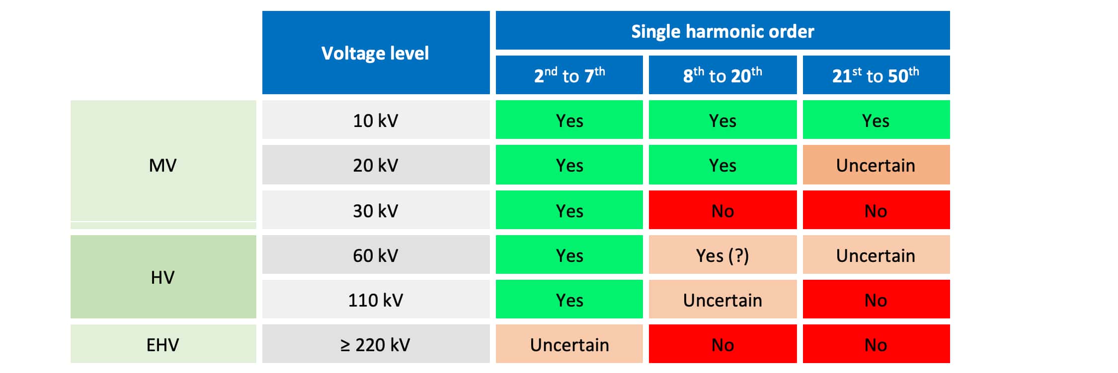
Certainly not all designs available on the market have been tested, so outliers in both the positive and negative direction must be expected. Many end users believe that there is a strong attenuation of the higher-frequency components after the permitted bandwidth. This assumption often does not correspond to reality. The primary coil basically forms resonance points which can strongly attenuate but also amplify the primary signal transformed to the secondary side. Amplitude errors of 200 to 400 % are possible here.7 The resonance points can also be combined with phase errors greater than 90 °.
In general, for inductive voltage transformers, the higher the voltage level, the closer the first resonance point is to the nominal frequency. For this reason, a measurement of harmonics in the extra-high voltage network from the 2nd to the 7th is no longer assured.
Digital energy meters and voltage transformers
While problems are primarily seen here in the measurement of voltage quality, problems also arise for billing measurement. This is because current energy meters in many cases have a larger analog bandwidth than the voltage transformer. This means that harmonics beyond the nominal frequency are passed on to the meter, sometimes significantly distorted. For example, the capacitive VT in Figure 4 amplifies an amplitude of 5% of the nominal voltage at 350 Hz by a factor of 1.6 and shifts its phase by about -20°. The distorted signal in blue is shown in the following diagram.
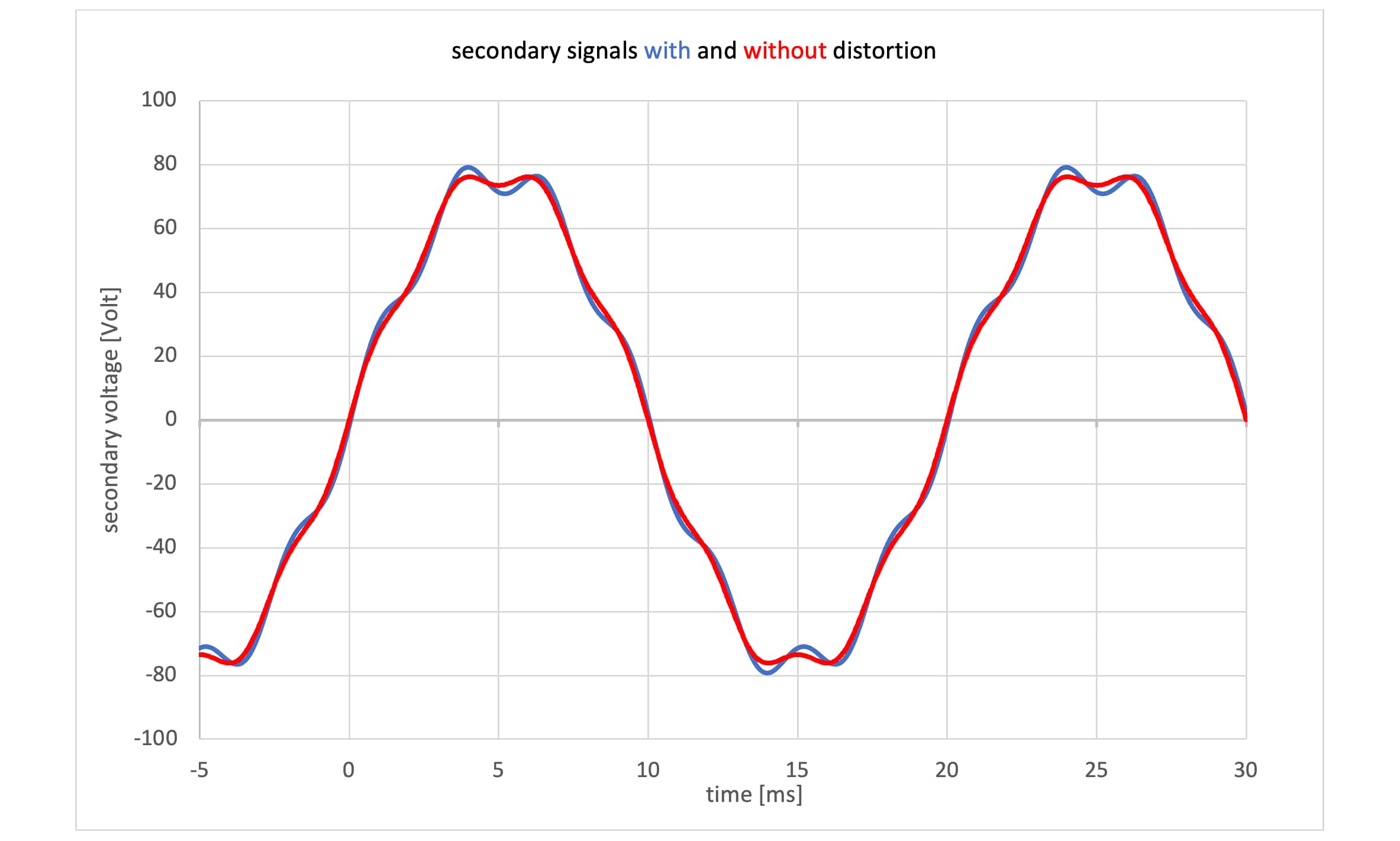
The voltage signal is then digitized in the meter at an appropriate sampling rate. Existing energy meters such as the LZQJ-XC have a sampling rate of 3.2 kHz. Statements regarding the analog bandwidth are unfortunately not found in the data sheet.8 Thus, it can be assumed that amplitudes at even higher frequencies are basically included in the active power calculation.
Power of a wind turbine
According to the international standard for wind turbines IEC 61400-219, the wind turbine is allowed a THDV and a THDI of maximum 5% up to 2.5 kHz. This means that a wind turbine specified with 5 MW only must have an active power of 4.5125 MW at nominal frequency.
(0.95 × V) × (0.95 × I) = 0.9025 × P = 4.5125 MW
The difference of 0.4875 MW can therefore also be provided at higher frequencies up to 2.5 kHz. A measurement at the high-voltage coupling point with capacitive or inductive voltage transformers could thus lead to strongly distorted power measurement values at higher frequency components. For the following example calculation, it is assumed that the complete distortion active power is provided on the 7th harmonic. Two scenarios are shown in the table below. In the first scenario, the percent distortion is +60 percent at 350 Hz, as shown in Figure 4. In the second scenario, a strong attenuation of -75 percent is assumed, which would also be realistic. The phase error is not taken into account in either case.
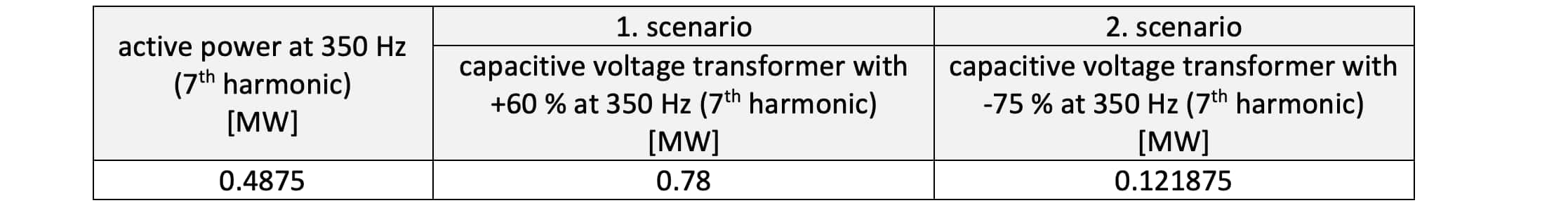
Even if the assumption that the entire power of 0.4875 MW is provided on the 7th harmonic does not correspond to reality, the example still shows that a larger analog bandwidth of the voltage transformers would be desirable, at least for one contracting partner.
Standardization trends regarding frequency response in IEC 61869-1
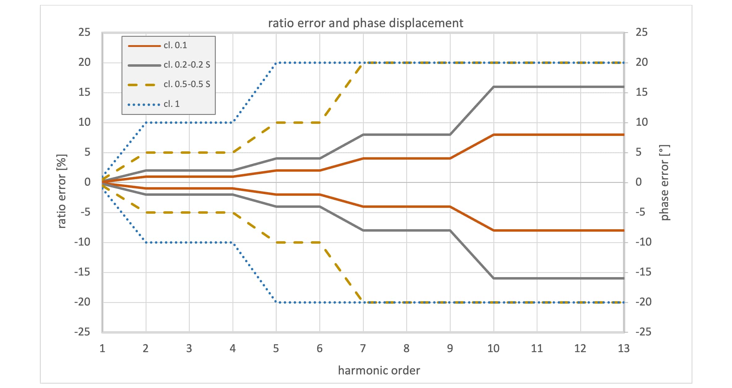
Due to the increasing importance of harmonics in a wide variety of measurement applications, accuracy values for different frequency ranges are listed in the already adopted final draft (AFDIS) of IEC 61869-1. Five extension levels for the measurement of harmonics are to apply to the known accuracy classes. These are called WB0 to WB4. The extension WB0 is to be interpreted as the lowest level and is only defined up to the 13th harmonic. It is mandatory for sensors (LPITs) and SAMUs. Accordingly, the defined accuracies are not very restrictive.
However, the LZQJ-XC instrument transformer energy meter has a larger analog bandwidth and a sampling rate of 3.2 kHz. This means that regarding a serious active power measurement, accuracies of up to at least 5 kHz are advisable, because the high-energy pulse frequencies of wind turbines are usually between 2 and 4 kHz. In the type test of the wind turbine, the power measurement is usually carried out on the low-voltage side. The Fluxgate current transducers used for laboratory applications provide highly accurate measured values up to at least 5 kHz.10
In addition to class WB0, classes WB1 to WB4 for instrument transformers are currently defined as follows.
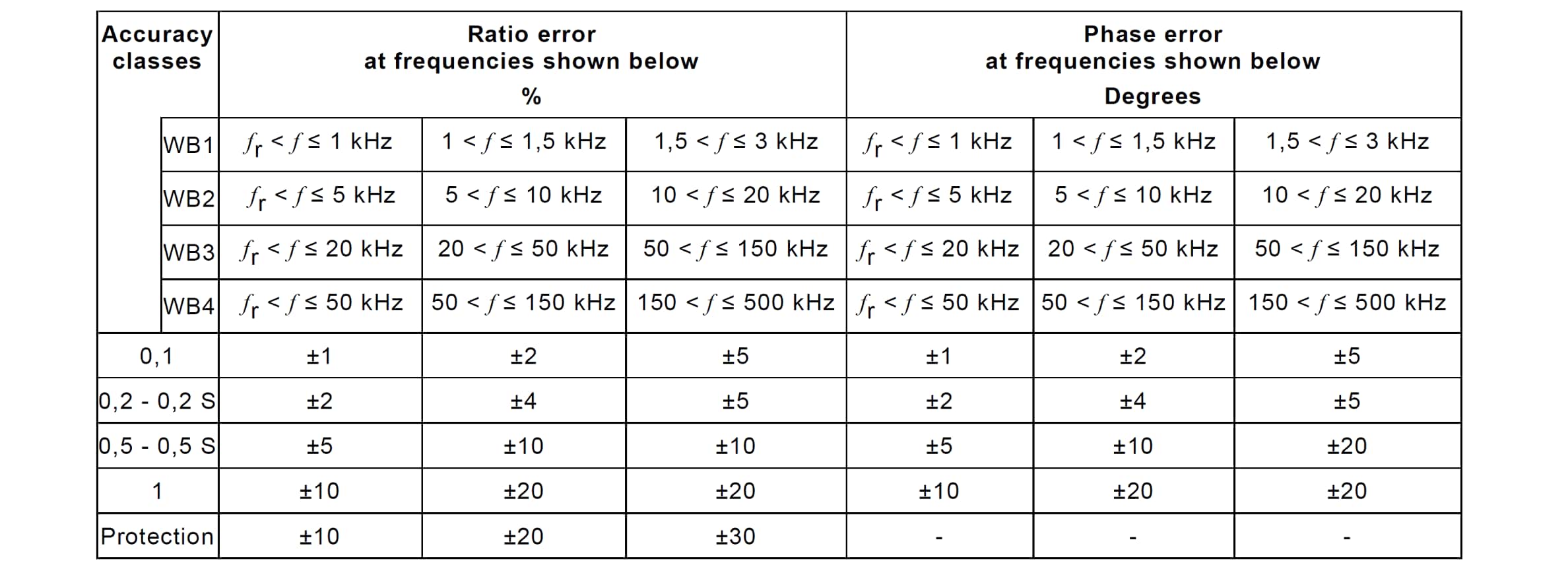
If the power measurement at the connection point is also to be carried out without distortion up to 5 kHz, class WB1 is not sufficient. This is only defined up to 3 kHz. Class WB2 is defined up to 20 kHz and is certainly a good choice. With regard to the bandwidth, it becomes clear that inductive or capacitive voltage transformers should no longer be used for power measurement in any case, even if only small amplitudes are to be expected at higher frequencies. Otherwise, the meter manufacturer would have to limit the analog bandwidth for active power calculation to almost nominal frequency.
In the future, the customer should be able to optionally specify the accuracy classes for harmonics according to the table shown above when ordering the instrument transformer. For example, this would result in the following specification:
accuracy class 0.2-WB2
Technology change in voltage measurement
It can be stated that a technology change in the field of voltage measurement from 123 kV must take place if the energy meters continue to have a larger analog bandwidth than the voltage transformers. The Swiss manufacturer of high-voltage equipment CONDIS SA has responded to the need for broadband voltage transformers and offers CR dividers for the voltage range of 123 kV. The use of these sensors in billing measurement is to be evaluated as permissible in Germany and in many other countries due to the applicable regulations.
Due to the principle of operation, it is a Low Power Instrument Transformer (LPIT) in contrast to the traditionally used devices, which cannot provide the conventional power on the secondary side. However, this circumstance should not be an issue. Like the traditional devices, a signal of 100/√3 volts is also provided on the secondary side. When selecting the energy meter, it is important to ensure that the electrical supply is delivered by a separate power supply and is not provided through the voltage measurement channels. Furthermore, the meter manufacturer must specify the exact input impedance of the meter for the voltage channels. In the case of the LZQJ-XC, this results in 880.680 kOhm. In principle, it is also possible to operate meters in parallel. In this case, only the total impedance must be calculated. A value above 250 kOhm is generally considered as feasible.
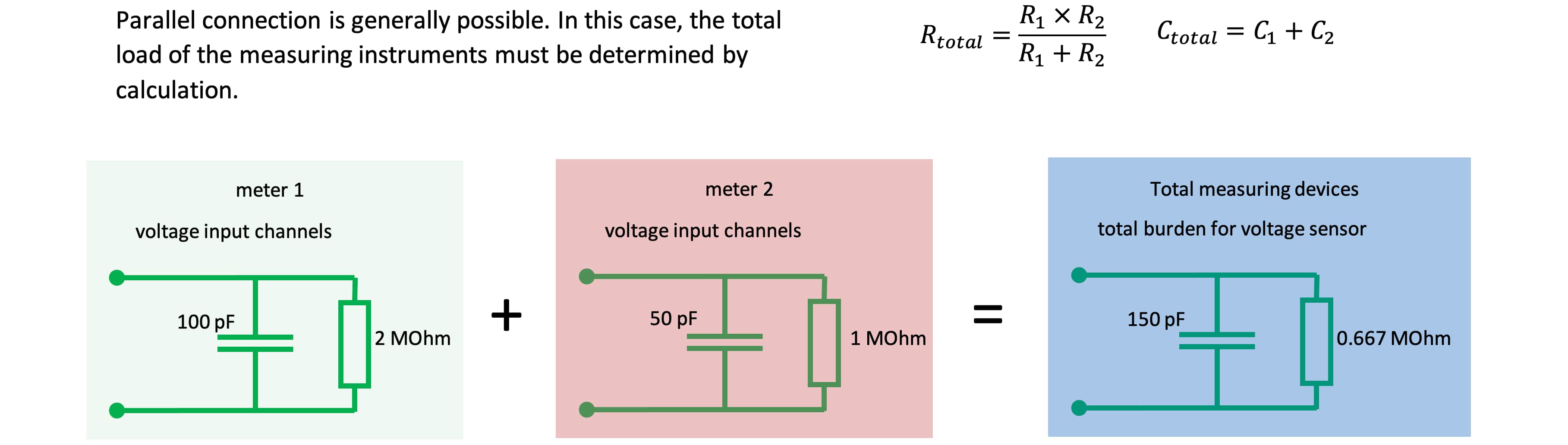
In addition, the cable length from the sensor to the measuring devices must be specified precisely, since the impedance of the cable is also included in the calculation. In addition to energy meters, power quality analyzers can thus also be operated in parallel on one sensor.
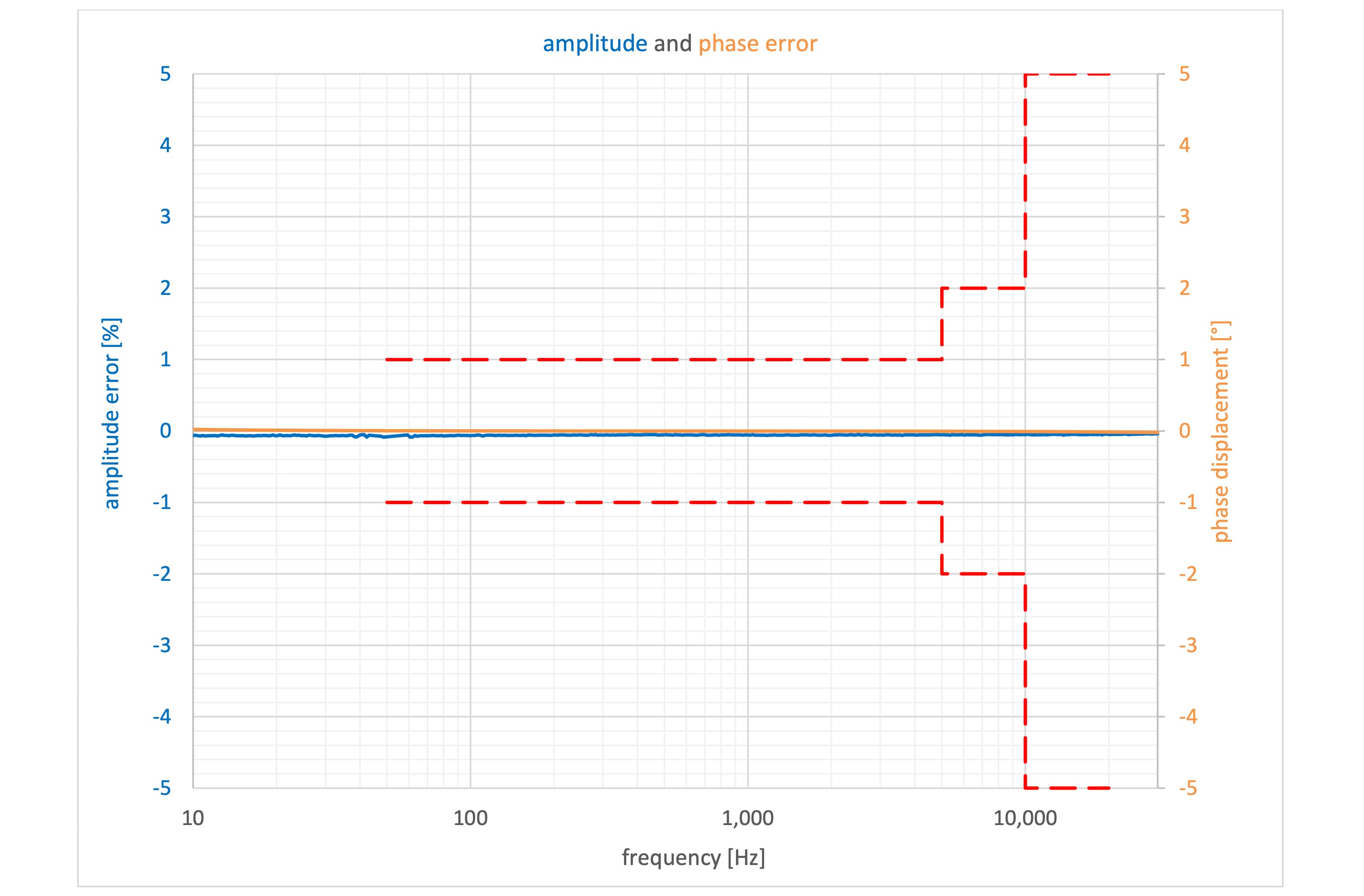
While the above CR divider is only used for power quality measurements, class 0.1 in combination with frequency class WB2 have been realized for a metering CR divider with Um=123 kV which can be used for settlement purposes.
Current transformer
Like the measurement technology for voltage measurement with Um ≥ 123 kV, the technology for current measurement is also freely selectable. This also applies if a current transformer isolated to low voltage is installed at the bushings of the switchgear or power transformer. There are two reasons for this statement:
1. Current transformer with insulation coordination (0.72 / 3 / - kV) is only the secondary part of a instrument transformer. The complete instrument transformer is located in a system with Um ≥ 123 kV.
2. The primary side of the instrument transformer (here the bushing) is also specified for insulation coordination with Um ≥ 123 kV.
Here, too, the inductive current transformers described in the PTB test rules were used in the past. The secondary current ratings are specified with 1 and 5 A. Accordingly, many instrument transformer meters are equipped with 1 or 5 A current measurement inputs. If class WB2 up to 20 kHz is selected here as well, care should be taken to ensure that the manufacturer takes the connecting cable to the metering device into account when specifying class WB2 for frequency measurement. It is not uncommon for one-way lengths of 100 to 300 m to occur. At higher frequencies, the inductances and capacitances of the cable can negatively affect the accuracy at higher frequencies.
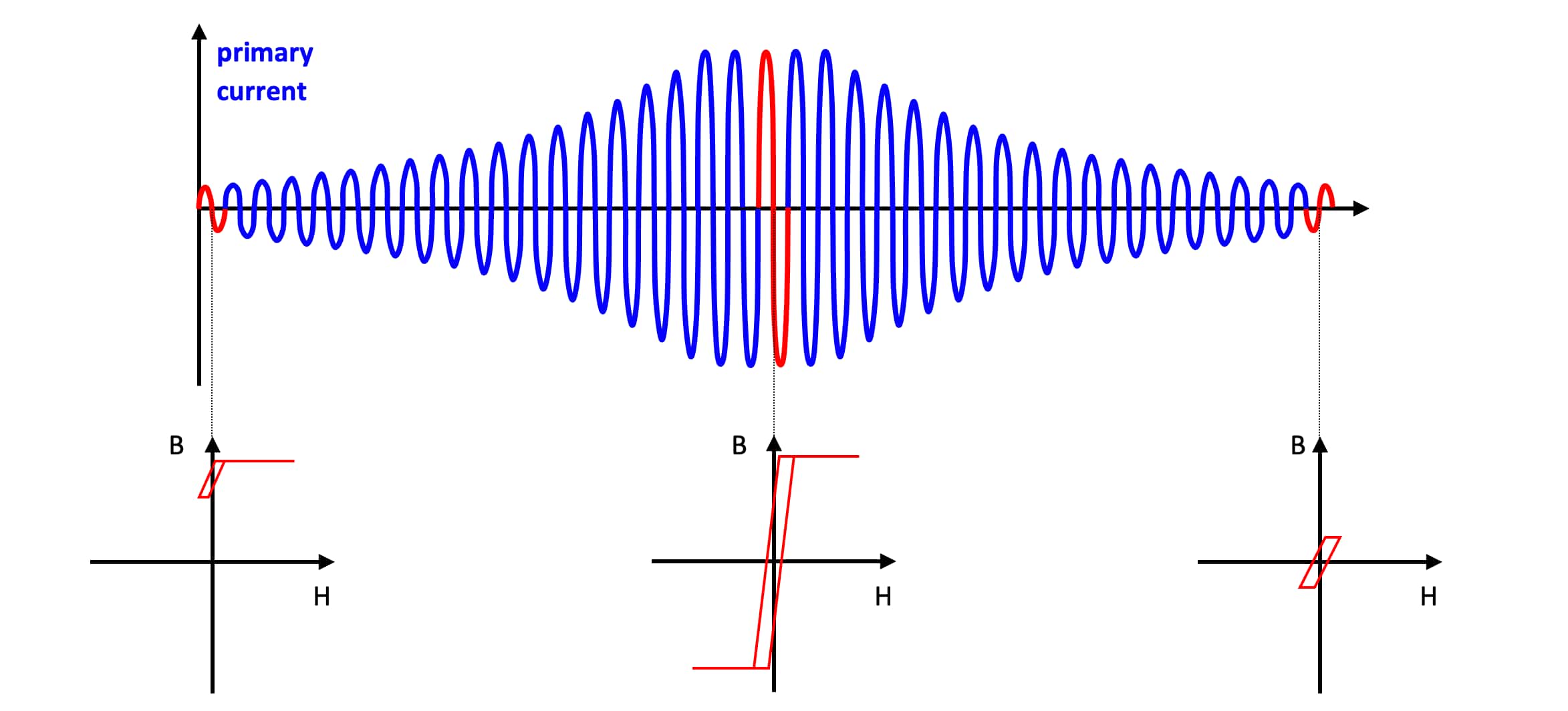
While in the literature current transformers are said to have a much better frequency response than voltage transformers, switching operations can cause the iron core to have residual magnetization. The reason for this is that the current is switched off at zero crossing. At this point, the magnetic flux density is exactly at its maximum due to the 90° shift. Particularly in the case of hard magnetic core materials without following excitation with the entire rated primary current and full burden power, the hysteresis curve does not always return to the starting point.11 The current transformer remains in a magnetic operating range which has not been specified and tested.12
But parasitic DC currents such as GICs can also shift the magnetic operating point of current transformers. The University of Stuttgart has proven that for an investigated current transformer with the measurement class 0.2S, the accuracy class was already left at 100 mA DC.13
The company Senseleq is a joint venture of the Dutch instrument transformer manufacturer Eleq and the Danish supplier of high-precision laboratory current transducers Danisense. These current transducers are based on the fluxgate principle and are used in test laboratories of wind turbine manufacturers, among others. These precision sensors can also be supplied in traditional designs for grid applications and ensure current measurement from DC to the double-digit kHz range in the high-voltage grid. In addition to power measurement, the harmonic measurements required in many national grid standards can also be realized in this way.14
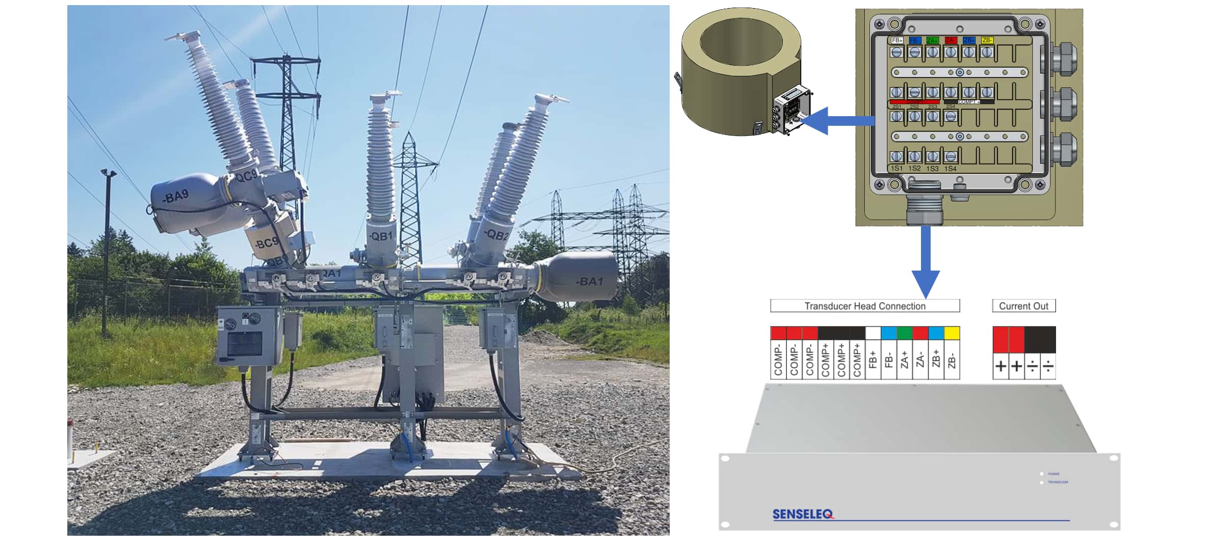
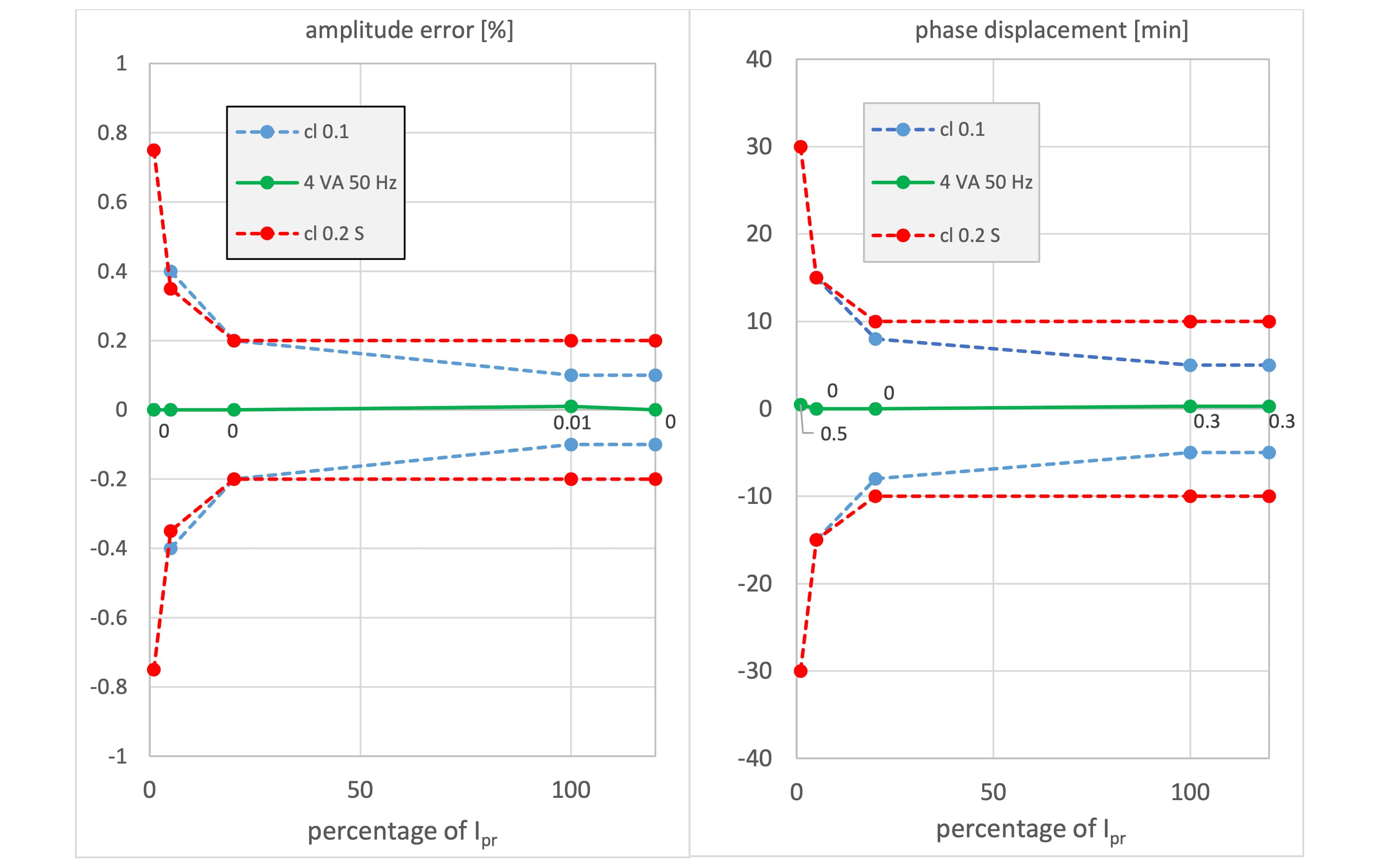
Among other things, the output signal of the fluxgate current transformer is 1 A at nominal current and can therefore be used with the existing instrument transformer meters on the market. Even with smaller primary currents, no major inaccuracies in amplitude or phase angle are to be expected.
In addition to the high accuracy at nominal system frequency, harmonic currents up to 50 kHz can be analyzed simultaneously in the above project. A PQ analyzer from Neo Messtechnik GmbH is used for this purpose, which has a sampling rate of 1 MS/s. The loupe function in the FFT analysis can even make GICs visible in the range from 0 to 1 Hz.15
Conclusion
The latest standard proposal regarding defined bandwidths for the known accuracy classes of instrument transformers is generally welcomed. Unfortunately, regarding the defined accuracy classes for higher-frequency components, the standard proposal only refers to PQ measurements and protection applications in the area of traveling waves. Defined bandwidths should also be considered in the future for power and billing measurements. It can be assumed that in the next few years there will have to be a technology change towards broadband sensors regarding voltage measurement. Fluxgate current transducers can also meet all future measurement requirements for current measurement and guarantee significantly better accuracy than conventional current transformers, especially in billing measurement. A delay of the technology change by the responsible authorities is not to be expected for Um ≥ 123 kV. The first projects in Europe have already been realized.
Authors
Roland Buerger (Senseleq B.V.): roland.buerger@senseleq.com
Dr. Thomas Heid (CONDIS SA): theid@condis.ch
Sources
1 PTB: Checklist for conformity evaluation procedures for instrument transformers
2 PTB requirements: Measuring instruments for electricity - Instrument transformers for electricity meters (PTB-A 20.2)
3 Verordnung über das Inverkehrbringen und die Bereitstellung von Messgeräten auf dem Markt sowie über ihre Verwendung und Eichung (Mess- und Eichverordnung - MessEV)
4 European Network of Transmission System Operators for Electricity (ENTSO-E)
5 etz Heft 6/2012: Components & Periphery – Frequency Response of Instrument Transformers in the kHz range
6 TRENCH CVT
7 https://powerquality.blog/2020/11/24/accuracy-of-harmonic-voltage-measurements-in-the-frequency-range-up-to-5khz-using-conventional-instrument-transformers/
8 https://emh-metering.com/wp-content/uploads/2021/06/LZQJXC-DAB-E-3.35_web.pdf
9 IEC 61400-21 Wind turbines – Part 21: Measurement and assessment of power quality characteristics of grid connected wind turbines
10 Danisense DR5000IM
11 O.W. Iwanusiw: Effect of Remanence on Metering Accuracy of 230-kV Current Transformers, Ontario Hydro Research Quarterly, 2nd and 3rd quarter, 1976, pp. 11-13
12 IEC 61869-6:2016 page 62
13 VDE-Hochspannungstechnik 2018, 12.-14.11.2018 in Berlin: Beeinflussung von induktiven Stromwandlern in Hoch- und Höchstspannungsnetzen durch parasitäre Gleichströme
14 Technische Anschlussregel Höchstspannung (VDE-AR-N 4130):2018 – 5.4.4 Harmonische, Zwischenharmonische und höherfrequente Emission
15 PQA 8000
16 CIGRE / CIRED Guidelines for Power Quality Monitoring WG C4.112 TECHNICAL BROCHURE 596


